 |
数据搜索系统,热门电子元器件搜索 |
|
|
数据搜索系统,热门电子元器件搜索 |
|
The question interval is too short.
Please try again in a few seconds.

Hello, Please ask a question about DRS-D-F Datasheet
# Example questions:
➢ Describe the function of the 'loop test selector' and how the options /e and /e2 affect its operation.
➢ What are the allowable input ranges for the rtd sensors this device supports?
➢ What specific connection must be made for high-temperature rtd sensors to ensure proper operation?
| Part No. | DRS-D-F |
| Manufacturer | MSYSTEM |
| Size | 118 Kbytes |
| Pages | 4 pages |
| Description | Plug-in Signal Conditioners M-UNIT |


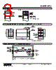


1. Product Overview: DRS (Likely a Temperature/Resistance Transmitter)
️· Function: The DRS is a device designed to read and transmit data, almost certainly related to temperature or resistance (given the RTD connection and mention of constant current). It's likely a transmitter, meaning it takes a sensor input and converts it into a standard output signal (likely 4-20mA or similar) for remote monitoring or control systems.
️· RTD Connection: "RTD" stands for Resistance Temperature Detector. This is a key sensor type used to measure temperature. The specification highlights the importance of connecting a "high temp" RTD to terminal #3. This indicates that the device likely has specific circuitry optimized for different RTD temperature ranges.
️· Options /E & /E2: These are optional features that likely expand the device's capabilities. It's important to determine what they enable (see below under "Further Analysis").
2. Technical Specifications & Performance
️· Input: Accepts RTD resistance measurements.
️· Output: "Differential Output" and "Constant Current Loop." The schematic suggests a 4-20mA signal.
️· Accuracy: Not explicitly stated but assumes adequate for industrial applications.
️· Power Requirements: Not explicitly stated but would be based on common industrial voltage power.
️· Ambient Conditions: Not explicitly stated.
️· Communication: Possibly, though no mention of digital communication (e.g., Modbus, HART) is provided.
3. Connection and Wiring
️· RTD Connection: Critical – connect high-temperature RTDs to terminal #3.
️· Power Input: Connected to terminals labeled "+” and “–".
️· Output Signal: Connected to terminals labeled “U(+)” and “V(–)".
️· Schematic: The wiring diagrams are essential for proper installation and should be followed precisely.
4. Key Takeaways & Potential Implications
️· RTD Range Adaptation: The device is designed to handle different RTD temperature ranges. Using the wrong RTD with the wrong terminal could lead to inaccurate readings or device damage.
️· Industrial Application: The device is likely intended for industrial environments.
️· 4-20mA Output: The "Constant Current Loop" strongly suggests a 4-20mA signal, which is a standard in industrial automation. This implies compatibility with PLCs, DCSs, and other control systems.
️· Potential for Advanced Features: Options /E and /E2 suggest the device has a modular design, and may have more functionality if added.
5. Needed Clarification and Further Analysis
️· What are the precise functions of options /E and /E2? (e.g., do they provide enhanced accuracy, diagnostics, or communication capabilities?)
️· What is the supported temperature range for the RTD input?
️· What is the input impedance?
️· What are the output signal characteristics (e.g., voltage range, accuracy, linearity)?
️· What is the device's level of isolation between power, signal, and sensor inputs?
️· Is there any digital communication available? (e.g., Modbus, HART)
1. Product Overview: DRS (Likely a Temperature/Resistance Transmitter)
️· Function: The DRS is a device designed to read and transmit data, almost certainly related to temperature or resistance (given the RTD connection and mention of constant current). It's likely a transmitter, meaning it takes a sensor input and converts it into a standard output signal (likely 4-20mA or similar) for remote monitoring or control systems.
️· RTD Connection: "RTD" stands for Resistance Temperature Detector. This is a key sensor type used to measure temperature. The specification highlights the importance of connecting a "high temp" RTD to terminal #3. This indicates that the device likely has specific circuitry optimized for different RTD temperature ranges.
️· Options /E & /E2: These are optional features that likely expand the device's capabilities. It's important to determine what they enable (see below under "Further Analysis").
2. Technical Specifications & Performance
️· Input: Accepts RTD resistance measurements.
️· Output: "Differential Output" and "Constant Current Loop." The schematic suggests a 4-20mA signal.
️· Accuracy: Not explicitly stated but assumes adequate for industrial applications.
️· Power Requirements: Not explicitly stated but would be based on common industrial voltage power.
️· Ambient Conditions: Not explicitly stated.
️· Communication: Possibly, though no mention of digital communication (e.g., Modbus, HART) is provided.
3. Connection and Wiring
️· RTD Connection: Critical – connect high-temperature RTDs to terminal #3.
️· Power Input: Connected to terminals labeled "+” and “–".
️· Output Signal: Connected to terminals labeled “U(+)” and “V(–)".
️· Schematic: The wiring diagrams are essential for proper installation and should be followed precisely.
4. Key Takeaways & Potential Implications
️· RTD Range Adaptation: The device is designed to handle different RTD temperature ranges. Using the wrong RTD with the wrong terminal could lead to inaccurate readings or device damage.
️· Industrial Application: The device is likely intended for industrial environments.
️· 4-20mA Output: The "Constant Current Loop" strongly suggests a 4-20mA signal, which is a standard in industrial automation. This implies compatibility with PLCs, DCSs, and other control systems.
️· Potential for Advanced Features: Options /E and /E2 suggest the device has a modular design, and may have more functionality if added.
5. Needed Clarification and Further Analysis
️· What are the precise functions of options /E and /E2? (e.g., do they provide enhanced accuracy, diagnostics, or communication capabilities?)
️· What is the supported temperature range for the RTD input?
️· What is the input impedance?
️· What are the output signal characteristics (e.g., voltage range, accuracy, linearity)?
️· What is the device's level of isolation between power, signal, and sensor inputs?
️· Is there any digital communication available? (e.g., Modbus, HART)
| Part No. | DRS-D-F |
| Manufacturer | MSYSTEM |
| Size | 118 Kbytes |
| Pages | 4 pages |
| Description | Plug-in Signal Conditioners M-UNIT |
| ALLDATASHEET是否为您带来帮助? [ DONATE ] |
关于 Alldatasheet | 广告服务 | 联系我们 | 隐私政策 | 数据表链接 | 链接交换 | 制造商名单 All Rights Reserved©Alldatasheet.com |
| Russian : Alldatasheetru.com | Korean : Alldatasheet.co.kr | Spanish : Alldatasheet.es | French : Alldatasheet.fr | Italian : Alldatasheetit.com Portuguese : Alldatasheetpt.com | Polish : Alldatasheet.pl | Vietnamese : Alldatasheet.vn Indian : Alldatasheet.in | Mexican : Alldatasheet.com.mx | British : Alldatasheet.co.uk | New Zealand : Alldatasheet.co.nz |
|
Family Site : ic2ic.com |
icmetro.com |
 Chinese ▼
  English
 German
 Japanese
 Russian
 Korean
 Spanish
 French
 Italian
 Portuguese
 Polish
 Vietnamese
 Indian
 Mexican
 British
 New Zealand