 |
数据搜索系统,热门电子元器件搜索 |
|
|
数据搜索系统,热门电子元器件搜索 |
|
The question interval is too short.
Please try again in a few seconds.

Hello, Please ask a question about 24LC04B-I/P Datasheet
# Example questions:
➢ What type of pull-up resistor is required for the sda bus, and what are the typical values for 100 khz and 400 khz speeds?
➢ Describe the difference between a sequential read and a random read operation, referencing how the master acknowledges data transmission in each case.
➢ What happens when the wp pin is tied to vcc?
| Part No. | 24LC04B-I/P |
| Manufacturer | MICROCHIP |
| Size | 419 Kbytes |
| Pages | 26 pages |
| Description | 4K I2C Serial EEPROM |


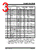


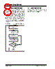


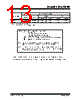


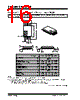






1. Overview & Function
️· Device Type: Serial EEPROM (Electrically Erasable Programmable Read-Only Memory).
️· Purpose: Non-volatile memory for storing data. The data is retained even when power is removed.
️· Communication: Uses the I²C (Inter-Integrated Circuit) serial communication protocol.
️· Capacity: 8 kbit (1024 bytes)
️· Organization: Single byte-erasable.
2. Key Features
️· I²C Compatible: Works with standard I²C bus architectures.
️· Wide Voltage Range: 1.7V to 5.5V supply voltage.
️· Fast Access Time: 10 ms maximum.
️· Write Protection:
- Software write protection (write disable).
- External hardware write protection (WP pin connected to VCC).
️· Low Power Consumption: Designed for low-power applications.
️· Noise Protection: Schmitt Trigger inputs and filter circuits.
️· Halts Operations Under Low Voltage: Prevents data corruption under low power conditions using a VCC threshold detector circuit.
️· Pb-Free: Available in Pb-free packages.
3. Pinout & Functions
️· A0, A1, A2: Not connected (NC). Can be left floating or tied to VSS/VCC.
️· VSS: Ground.
️· SDA: Serial Data/Address Input/Output – Bidirectional. Requires a pull-up resistor (10kΩ typical).
️· SCL: Serial Clock – Input.
️· WP: Write Protect – Input. Connected to VSS for normal operation; connected to VCC for write protection.
️· VCC: Power Supply (+1.7V to +5.5V).
4. I²C Communication Details
️· Address: Uses a 7-bit I²C slave address. (The document doesn't specify the default address but indicates it's configurable).
️· Data Transfer: SDA changes are permitted only during SCL low periods, indicating the start and stop conditions.
️· Addressing: Uses a 7-bit I²C slave address.
️· Data transfer: Data is transferred serially, one byte at a time.
5. Operational Modes (brief overview - document details each):
️· Write Mode: Data is written to the EEPROM. Requires a specific write sequence.
️· Read Mode: Data is read from the EEPROM.
️· Write Disable: Temporarily disables writing to the memory.
️· Hardware Write Protection: Uses the WP pin to completely disable writes.
6. Packaging Information
The document lists the available package types and marking codes:
️· PDIP
️· SOIC
️· TSSOP
️· DFN
️· MSOP
️· SOT-23
7. Important Notes & Caveats (READ THIS!)
️· Default I²C Address: The document *doesn't* explicitly state the default I²C slave address. You're expected to consult the datasheet for that crucial information.
️· Complete Datasheet Required: This summary is *not* a substitute for the full Microchip datasheet. This document highlights many features, but a complete understanding requires the full datasheet, which will cover timing diagrams, write sequences, detailed addressing, and all other nuances of operation.
️· External Components: You must provide the necessary external components, such as the pull-up resistor for SDA.
️· Datasheet is the Authority: Always refer to the official Microchip datasheet for the definitive and most up-to-date information. This summary is for quick reference only.
️· Pb-Free Conversion: Check the Microchip website ([www.microchip.com/Pbfree](http://www.microchip.com/Pbfree)) for the latest information on Pb-free conversion status.
1. Overview & Function
️· Device Type: Serial EEPROM (Electrically Erasable Programmable Read-Only Memory).
️· Purpose: Non-volatile memory for storing data. The data is retained even when power is removed.
️· Communication: Uses the I²C (Inter-Integrated Circuit) serial communication protocol.
️· Capacity: 8 kbit (1024 bytes)
️· Organization: Single byte-erasable.
2. Key Features
️· I²C Compatible: Works with standard I²C bus architectures.
️· Wide Voltage Range: 1.7V to 5.5V supply voltage.
️· Fast Access Time: 10 ms maximum.
️· Write Protection:
- Software write protection (write disable).
- External hardware write protection (WP pin connected to VCC).
️· Low Power Consumption: Designed for low-power applications.
️· Noise Protection: Schmitt Trigger inputs and filter circuits.
️· Halts Operations Under Low Voltage: Prevents data corruption under low power conditions using a VCC threshold detector circuit.
️· Pb-Free: Available in Pb-free packages.
3. Pinout & Functions
️· A0, A1, A2: Not connected (NC). Can be left floating or tied to VSS/VCC.
️· VSS: Ground.
️· SDA: Serial Data/Address Input/Output – Bidirectional. Requires a pull-up resistor (10kΩ typical).
️· SCL: Serial Clock – Input.
️· WP: Write Protect – Input. Connected to VSS for normal operation; connected to VCC for write protection.
️· VCC: Power Supply (+1.7V to +5.5V).
4. I²C Communication Details
️· Address: Uses a 7-bit I²C slave address. (The document doesn't specify the default address but indicates it's configurable).
️· Data Transfer: SDA changes are permitted only during SCL low periods, indicating the start and stop conditions.
️· Addressing: Uses a 7-bit I²C slave address.
️· Data transfer: Data is transferred serially, one byte at a time.
5. Operational Modes (brief overview - document details each):
️· Write Mode: Data is written to the EEPROM. Requires a specific write sequence.
️· Read Mode: Data is read from the EEPROM.
️· Write Disable: Temporarily disables writing to the memory.
️· Hardware Write Protection: Uses the WP pin to completely disable writes.
6. Packaging Information
The document lists the available package types and marking codes:
️· PDIP
️· SOIC
️· TSSOP
️· DFN
️· MSOP
️· SOT-23
7. Important Notes & Caveats (READ THIS!)
️· Default I²C Address: The document *doesn't* explicitly state the default I²C slave address. You're expected to consult the datasheet for that crucial information.
️· Complete Datasheet Required: This summary is *not* a substitute for the full Microchip datasheet. This document highlights many features, but a complete understanding requires the full datasheet, which will cover timing diagrams, write sequences, detailed addressing, and all other nuances of operation.
️· External Components: You must provide the necessary external components, such as the pull-up resistor for SDA.
️· Datasheet is the Authority: Always refer to the official Microchip datasheet for the definitive and most up-to-date information. This summary is for quick reference only.
️· Pb-Free Conversion: Check the Microchip website ([www.microchip.com/Pbfree](http://www.microchip.com/Pbfree)) for the latest information on Pb-free conversion status.
| Part No. | 24LC04B-I/P |
| Manufacturer | MICROCHIP |
| Size | 419 Kbytes |
| Pages | 26 pages |
| Description | 4K I2C Serial EEPROM |
| ALLDATASHEET是否为您带来帮助? [ DONATE ] |
关于 Alldatasheet | 广告服务 | 联系我们 | 隐私政策 | 数据表链接 | 链接交换 | 制造商名单 All Rights Reserved©Alldatasheet.com |
| Russian : Alldatasheetru.com | Korean : Alldatasheet.co.kr | Spanish : Alldatasheet.es | French : Alldatasheet.fr | Italian : Alldatasheetit.com Portuguese : Alldatasheetpt.com | Polish : Alldatasheet.pl | Vietnamese : Alldatasheet.vn Indian : Alldatasheet.in | Mexican : Alldatasheet.com.mx | British : Alldatasheet.co.uk | New Zealand : Alldatasheet.co.nz |
|
Family Site : ic2ic.com |
icmetro.com |
 Chinese ▼
  English
 German
 Japanese
 Russian
 Korean
 Spanish
 French
 Italian
 Portuguese
 Polish
 Vietnamese
 Indian
 Mexican
 British
 New Zealand