|
数据搜索系统,热门电子元器件搜索 |
|
|
数据搜索系统,热门电子元器件搜索 |
|
AM261...ZCZ 数据表(PDF) 155 Page - Texas Instruments |
|
|
|||||||||||||||||||||||||||||
AM261...ZCZ 数据表(HTML) 155 Page - Texas Instruments |
|
|
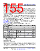
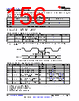
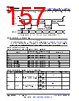
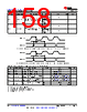
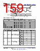
155 / 218 page  6.11.5.13 Octal Serial Peripheral Interface (OSPI) OSPI offers two data capture modes, PHY mode and Tap mode. PHY mode uses an internal reference clock to transmit and receive data via a DLL based PHY, where each reference clock cycle produces a single cycle of OSPI_CLK for Single Data Rate (SDR) transfers or a half cycle of OSPI_CLK for Double Data Rate (DDR) transfers. PHY mode supports three clocking topologies for the receive data capture clock. Internal PHY Loopback - uses the internal reference clock as the PHY receive data capture clock. Internal Pad Loopback - uses OSPI_LBCLKO looped back into the PHY from the OSPI_LBCLKO pin as the PHY receive data capture clock. DQS - uses the DQS output from the attached device as the PHY receive data capture clock. SDR transfers are not supported when using the Internal Pad Loopback and DQS clocking topologies. DDR transfers are not supported when using the Internal PHY Loopback or Internal Pad Loopback clocking topologies. Tap mode uses an internal reference clock with selectable taps to adjusted data transmit and receive capture delays relative to OSPI_CLK, which is a divide by 4 of the internal reference clock for SDR transfers or a divide by 8 of the internal reference clock for DDR transfers. Tap mode only supports one clocking topology for the receive data capture clock. No Loopback - uses the internal reference clock as the Tap receive data capture clock. This clocking topology supports a maximum internal reference clock rate of 200MHz, which produces an OSPI_CLK rate up to 50MHz for SDR mode or 25MHz for DDR mode. OSPI PHY Mode defines timing requirements and switching characteristics associated with PHY mode and OSPI Tap Mode defines timing requirements and switching characteristics associated with Tap mode. OSPI Timing Conditions presents timing conditions for OSPI. For more information, see Octal Serial Peripheral Interface (OSPI) section in the device TRM. 6.11.5.13.1 OSPI Timing Conditions PARAMETER MODE MIN MAX UNIT INPUT CONDITIONS SRI Input slew rate 2 6 V/ns OUTPUT CONDITIONS CL Output load capacitance 3 15 pF PCB CONNECTIVITY REQUIREMENTS td(Trace Delay) Propagation delay of OSPI_CLK trace(1) No Loopback Internal PHY Loopback Internal Pad Loopback 450 ps Propagation delay of OSPI_DQS trace DQS L(2) - 30 L(2) + 30 ps td(Trace Delay) Propagation delay of OSPI_LBCLKO trace External Board Loopback 2L(2) - 30 2L(2) + 30 ps td(Trace Mismatch Delay) Propagation delay mismatch of OSPI_D[7:0] and OSPI_CSn[1:0] relative to OSPI_CLK All modes 60 ps (1) Not applicable when using DQS clocking topology (2) L = Propagation delay of OSPI_CLK trace 6.11.5.13.2 OSPI PHY Mode 6.11.5.13.2.1 OSPI With PHY Data Training Read and write data valid windows will shift due to variation in process, voltage, temperature, and operating frequency. A data training method may be implemented to dynamically configure optimal read and write timing. Implementing data training enables proper operation across temperature with a specific process, voltage, and frequency operating condition, while achieving a higher operating frequency. www.ti.com AM2612, AM2611, AM2611-Q1, AM2612-Q1 SPRSPA7C – SEPTEMBER 2024 – REVISED JULY 2025 Copyright © 2025 Texas Instruments Incorporated Submit Document Feedback 155 Product Folder Links: AM2612 AM2611 AM2611-Q1 AM2612-Q1 |
|
链接网址 |
| ALLDATASHEET是否为您带来帮助? [ DONATE ] |
关于 Alldatasheet | 广告服务 | 联系我们 | 隐私政策 | 数据表链接 | 链接交换 | 制造商名单 All Rights Reserved©Alldatasheet.com |
| Russian : Alldatasheetru.com | Korean : Alldatasheet.co.kr | Spanish : Alldatasheet.es | French : Alldatasheet.fr | Italian : Alldatasheetit.com Portuguese : Alldatasheetpt.com | Polish : Alldatasheet.pl | Vietnamese : Alldatasheet.vn Indian : Alldatasheet.in | Mexican : Alldatasheet.com.mx | British : Alldatasheet.co.uk | New Zealand : Alldatasheet.co.nz |
|
Family Site : ic2ic.com |
icmetro.com |
 Chinese ▼
 English
 Chinese
 German
 Japanese
 Russian
 Korean
 Spanish
 French
 Italian
 Portuguese
 Polish
 Vietnamese
 Indian
 Mexican
 British
 New Zealand