 |
数据搜索系统,热门电子元器件搜索 |
|
|
数据搜索系统,热门电子元器件搜索 |
|
The question interval is too short.
Please try again in a few seconds.

Hello, Please ask a question about GD25LE32DQIG Datasheet
# Example questions:
➢ Describe the function of the wip and wel bits, and explain what each indicates regarding the device's current state and acceptance of commands.
➢ How do the bp4-bp0 bits, in conjunction with the cmp bit, determine the protected area of memory, and what command can still be executed even with protection enabled?
➢ What are the different methods of protecting the status register from being written to, as defined by the srp1 and srp0 bits, and how does the hardware protected mode function?
| Part No. | GD25LE32DQIG |
| Manufacturer | GIGADEVICE |
| Size | 1Mb |
| Pages | 72 pages |
| Description | 1.8V Uniform Sector Dual and Quad Serial Flash |









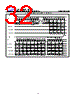
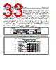


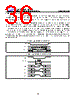

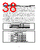















1. Key Features & Introduction:
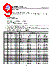
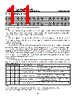
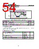
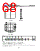
️· This is an excerpt from the datasheet for a GD25LE32D flash memory device.
2. Command Execution and Status:
️· WIP (Write In Progress): Indicates if the memory is busy with programming, erasing, or writing to the status register. `WIP = 1` means busy, `WIP = 0` means idle.
️· WEL (Write Enable Latch): Controls whether write operations (status register, programming, erasing) are allowed. `WEL = 1` enables writing, `WEL = 0` disables it.
3. Block Protection (BP4-BP0):
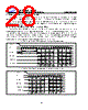
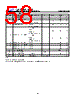
️· These bits define software-protected memory areas. When set (`BP = 1`), certain commands (Program, Erase) are blocked in the corresponding memory region.
️· The specific protection size is defined by Table 1 and Table 2 in the complete datasheet.
️· BP bits can be written using the Write Status Register (WRSR) command, but only if hardware protection isn't enabled.
️· Chip Erase behavior depends on the value of these bits and the CMP (Compare) bit.
4. Status Register Protection (SRP1, SRP0):
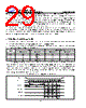
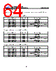
️· These bits control how the status register is protected. They influence whether the status register can be modified and under what conditions.
️· They are non-volatile, meaning they persist through power cycles.
SRP1 & SRP0 Combinations and their Meanings:
| SRP1 | SRP0 | #WP (Hardware Protection Input) | Status Register Protection |
|---|---|---|---|
| 0 | 0 | X | Software Protected (Default) - Writeable after WEL=1 |
| 0 | 1 | 0 | Hardware Protected - Locked, writeable only if WP#=0 |
| 0 | 1 | 1 | Hardware Unprotected - Writeable after WEL=1 and WP#=1 |
| 1 | 0 | X | Power Supply Lock-Down - Requires Power-Down/Up cycle to reset |
| 1 | 1 | X | One-Time Programmable - Permanently protected |
1. Key Features & Introduction:
️· This is an excerpt from the datasheet for a GD25LE32D flash memory device.
2. Command Execution and Status:
️· WIP (Write In Progress): Indicates if the memory is busy with programming, erasing, or writing to the status register. `WIP = 1` means busy, `WIP = 0` means idle.
️· WEL (Write Enable Latch): Controls whether write operations (status register, programming, erasing) are allowed. `WEL = 1` enables writing, `WEL = 0` disables it.
3. Block Protection (BP4-BP0):
️· These bits define software-protected memory areas. When set (`BP = 1`), certain commands (Program, Erase) are blocked in the corresponding memory region.
️· The specific protection size is defined by Table 1 and Table 2 in the complete datasheet.
️· BP bits can be written using the Write Status Register (WRSR) command, but only if hardware protection isn't enabled.
️· Chip Erase behavior depends on the value of these bits and the CMP (Compare) bit.
4. Status Register Protection (SRP1, SRP0):
️· These bits control how the status register is protected. They influence whether the status register can be modified and under what conditions.
️· They are non-volatile, meaning they persist through power cycles.
SRP1 & SRP0 Combinations and their Meanings:
| SRP1 | SRP0 | #WP (Hardware Protection Input) | Status Register Protection |
|---|---|---|---|
| 0 | 0 | X | Software Protected (Default) - Writeable after WEL=1 |
| 0 | 1 | 0 | Hardware Protected - Locked, writeable only if WP#=0 |
| 0 | 1 | 1 | Hardware Unprotected - Writeable after WEL=1 and WP#=1 |
| 1 | 0 | X | Power Supply Lock-Down - Requires Power-Down/Up cycle to reset |
| 1 | 1 | X | One-Time Programmable - Permanently protected |
| Part No. | GD25LE32DQIG |
| Manufacturer | GIGADEVICE |
| Size | 1Mb |
| Pages | 72 pages |
| Description | 1.8V Uniform Sector Dual and Quad Serial Flash |
| ALLDATASHEET是否为您带来帮助? [ DONATE ] |
关于 Alldatasheet | 广告服务 | 联系我们 | 隐私政策 | 数据表链接 | 链接交换 | 制造商名单 All Rights Reserved©Alldatasheet.com |
| Russian : Alldatasheetru.com | Korean : Alldatasheet.co.kr | Spanish : Alldatasheet.es | French : Alldatasheet.fr | Italian : Alldatasheetit.com Portuguese : Alldatasheetpt.com | Polish : Alldatasheet.pl | Vietnamese : Alldatasheet.vn Indian : Alldatasheet.in | Mexican : Alldatasheet.com.mx | British : Alldatasheet.co.uk | New Zealand : Alldatasheet.co.nz |
|
Family Site : ic2ic.com |
icmetro.com |
 Chinese ▼
  English
 German
 Japanese
 Russian
 Korean
 Spanish
 French
 Italian
 Portuguese
 Polish
 Vietnamese
 Indian
 Mexican
 British
 New Zealand