|
数据搜索系统,热门电子元器件搜索 |
|
|
数据搜索系统,热门电子元器件搜索 |
|
AD1583ART-R2 数据表(PDF) 12 Page - Analog Devices |
|
|
|||||||||||||||||||||||||||||
AD1583ART-R2 数据表(HTML) 12 Page - Analog Devices |
|
|
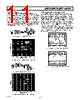
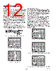
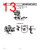
12 / 16 page  AD1582/AD1583/AD1584/AD1585 –12– REV. D TURN-ON TIME Many low power instrument manufacturers are becoming increas- ingly concerned with the turn-on characteristics of the components being used in their systems. Fast turn-on components often enable the end user to save power by keeping power off when it is not needed. Turn-on settling time is defined as the time required, after the application of power (cold start), for the output voltage to reach its final value within a specified error. The two major factors affecting this are the active circuit settling time and the time required for the thermal gradients on the chip to stabilize. Figure 12a shows the turn-on settling and transient response test circuit. Figure 12b shows the turn-on characteristic of the AD1582. This characteristic is generated from cold-start operation and represents the true turn-on waveform after power-up. Figure 12c shows the fine settling characteristics of the AD1582. Typically, the reference settles to within 0.1% of its final value in about 100 µs. The device can momentarily draw excessive supply current when VSUPPLY is slightly below the minimum specified level. Power supply resistance must be low enough to ensure reliable turn-on. Fast power supply edges minimize this effect. 0V OR 10V 0V TO 10V 5V OR 10V 0V OR 5V 0.22 F DUT 0.22 F VOUT 10k 10k 1 Figure 12a. Turn-On/Transient Response Test Circuit 10 0% 100 90 20 s 5V 20 s 1V Figure 12b. Turn-On Characteristics 10 0% 100 90 20 s 5V 20 s 1mV Figure 12c. Turn-On Settling DYNAMIC PERFORMANCE Many A/D and D/A converters present transient current loads to the reference, and poor reference response can degrade the converter’s performance. The AD1582/AD1583/AD1584/AD1585 family of references provides superior static and dynamic line and load regulation. Since these series references are capable of both sourcing and sinking large current loads, they exhibit excellent settling characteristics. Figure 13 displays the line transient response for the AD1582. The circuit used to perform such a measurement is shown in Figure 12a, where the input supply voltage is toggled from 5 V to 10 V and the input and output capacitors are each 0.22 µF. Figures 14 and 15 show the load transient settling characteristics for the AD1582 when load current steps of 0 mA to +5 mA and 0 mA to –1 mA are applied. The input supply voltage remains constant at 5 V, the input decoupling and output load capacitors are 4.7 µF and 1 µF, respectively, and the output current is toggled. For both positive and negative current loads, the reference responses settle very quickly and exhibit initial voltage spikes less than 10 mV. 10 0% 100 90 50 s 5V 50 s 200mV Figure 13. Line Transient Response 10 0% 100 90 20 s 5V 20 s 5mV Figure 14. Load Transient Response (0 mA to 5 mA Load) 10 0% 100 90 20 s 5V 20 s 5mV Figure 15. Load Transient Response (0 mA to –1 mA Load) |
|
|
链接网址 |
| ALLDATASHEET是否为您带来帮助? [ DONATE ] |
关于 Alldatasheet | 广告服务 | 联系我们 | 隐私政策 | 数据表链接 | 链接交换 | 制造商名单 All Rights Reserved©Alldatasheet.com |
| Russian : Alldatasheetru.com | Korean : Alldatasheet.co.kr | Spanish : Alldatasheet.es | French : Alldatasheet.fr | Italian : Alldatasheetit.com Portuguese : Alldatasheetpt.com | Polish : Alldatasheet.pl | Vietnamese : Alldatasheet.vn Indian : Alldatasheet.in | Mexican : Alldatasheet.com.mx | British : Alldatasheet.co.uk | New Zealand : Alldatasheet.co.nz |
|
Family Site : ic2ic.com |
icmetro.com |
 Chinese ▼
 English
 Chinese
 German
 Japanese
 Russian
 Korean
 Spanish
 French
 Italian
 Portuguese
 Polish
 Vietnamese
 Indian
 Mexican
 British
 New Zealand