|
数据搜索系统,热门电子元器件搜索 |
|
|
数据搜索系统,热门电子元器件搜索 |
|
L8001L-R20-R 数据表(PDF) 5 Page - Unisonic Technologies |
|
|
|||||||||||||||||||||||||||||
L8001L-R20-R 数据表(HTML) 5 Page - Unisonic Technologies |
|
|
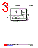
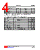
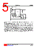
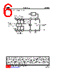
5 / 6 page  L8001 Preliminary CMOS IC UNISONIC TECHNOLOGIES CO., LTD 5 of 6 www.unisonic.com.tw QW-R502-938.d T Y PI CAL APPLI CAT I ON CI RCU I T There are three major functions provided by L8001G: support negative voltage, bias control circuit, and FET protesting circuit. The negative voltage is generated using internal oscillator. It only needs an ac coupled capacitor CNB 47nF and a negative voltage bypass capacitor CSUB 47nF. The bias control circuit is used to establish a stable bias current for FETs. It’s bias current can be adjusted by external resistor Rcal.Rcal1 resistor is used to set ID1, ID2, ID3 in L8001G. Rcal2 resistor is used to set ID4, ID5, ID6 in L8001G. if the same drain current is required for all FETs then pins Ical1 and Ical2 can be wired together and shunted to ground by a single resistor of half normal value. The L8001G devices have been designed to protect the external FETs from adverse operating conditions. With a JFET connected to any bias circuit, the gate output voltage of the bias circuit can not exceed the range -2.5V to 0.7V, under any conditions including powerup and powerdown transients. Should the negative bias generator be shorted or overloaded so that the drain current of the external FETs can no longer be controlled, the drain supply to FETs is shut down to avoid damage to the FETs by excessive drain current. The following diagrams show the L8001G in typical LNB applications. Within each FET gain stage the numbering system indicates how the bias stages relate to the application circuits. This is important when RCAL values are used to set differing drain currents. |
|
|
链接网址 |
| ALLDATASHEET是否为您带来帮助? [ DONATE ] |
关于 Alldatasheet | 广告服务 | 联系我们 | 隐私政策 | 数据表链接 | 链接交换 | 制造商名单 All Rights Reserved©Alldatasheet.com |
| Russian : Alldatasheetru.com | Korean : Alldatasheet.co.kr | Spanish : Alldatasheet.es | French : Alldatasheet.fr | Italian : Alldatasheetit.com Portuguese : Alldatasheetpt.com | Polish : Alldatasheet.pl | Vietnamese : Alldatasheet.vn Indian : Alldatasheet.in | Mexican : Alldatasheet.com.mx | British : Alldatasheet.co.uk | New Zealand : Alldatasheet.co.nz |
|
Family Site : ic2ic.com |
icmetro.com |
 Chinese ▼
 English
 Chinese
 German
 Japanese
 Russian
 Korean
 Spanish
 French
 Italian
 Portuguese
 Polish
 Vietnamese
 Indian
 Mexican
 British
 New Zealand