|
数据搜索系统,热门电子元器件搜索 |
|
|
数据搜索系统,热门电子元器件搜索 |
|
R110-R 数据表(PDF) 2 Page - Eaton All Rights Reserved. |
|
|
|||||||||||||||||||||||||||||
R110-R 数据表(HTML) 2 Page - Eaton All Rights Reserved. |
|
|
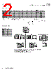
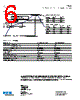
2 / 6 page  2 Technical Data 4373 Effective September 2017 FP0404 High frequency, high current power inductors www.eaton.com/electronics Product Specifications Part Number5 OCL1 (nH) ±15% FLL2 (nH) minimum I rms 3 (A) I sat1 4 (A) I sat2 5 (A) I sat3 6 (A) DCR (mΩ) @ +20 °C ±25% K-factor7 FP0404R1-R022-R 22 ±20% 15 19 40 34 32 0.32 ± 15% 2351 FP0404R1-R065-R 65 44 19 24 22 20 0.32 2248 FP0404R1-R080-R 80 54 19 20 18 16 0.32 2248 FP0404R1-R100-R 100 68 19 16 14 13 0.32 2248 FP0404R1-R110-R 110 74 19 14 13 12 0.32 2248 1. Open Circuit Inductance (OCL) Test Parameters: 100 kHz (1 MHz for R022), 0.1 Vrms, 0.0 Adc, +25 °C 2. Full Load Inductance (FLL) Test Parameters: 100 kHz (1 MHz for R022), 0.1 Vrms, Isat1, +25 °C 3. Irms: DC current for an approximate temperature rise of 40 °C without core loss. Derating is necessary for AC currents. PCB layout, trace thickness and width, air-flow, and proximity of other heat generating components will affect the temperature rise. It is recommended that the temperature of the part not exceed +125 °C underworst case operating conditions verified in the end application. 4. Isat1 : Peak current for approximately 20% rolloff @ +25 °C 5. Isat2 : Peak current for approximately 20% rolloff @ +100 °C 6. Isat3 : Peak current for approximately 20% rolloff @ +125 °C 7. K-factor: Used to determine Bp-p for core loss (see graph). Bp-p = K * L * ∆I * 10-3. Bp-p:(Gauss), K: (K-factor from table), L: (Inductance in nH), ∆I (Peak to peak ripple current in Amps). 8. Part Number Definition: FP0404-Rxxx-R FP0404 = Product code and size Rx= DCR indicator Rxxx=Inductance value in μH, R=decimal point -R suffix = RoHS compliant Dimensions (mm) Part Number C max R022-R 3.0 R065-R 4.0 R080-R 4.0 R100-R 4.0 R110-R 4.0 Part marking: Rxxx xxx=inductance value in uH, R=decimal point, wly= date code All soldering surfaces to be coplanar within 0.1 millimeters DCR is measured from paoint “a” to point “b” Do not route traces or vias underneath the inductor Recommended Pad Layout Schematic 4.0 max 4.0 max 1 2 (R065, R080, R100, R110) (R022) 1.4 ±0.20 1.2 ±0.20 1.4 ±0.30 1.4 ±0.20 1.2 ±0.20 1.4 ±0.30 1 2 4.2 4.3 1.7 1.7 0.9 1.9 |
|
|
链接网址 |
| ALLDATASHEET是否为您带来帮助? [ DONATE ] |
关于 Alldatasheet | 广告服务 | 联系我们 | 隐私政策 | 数据表链接 | 链接交换 | 制造商名单 All Rights Reserved©Alldatasheet.com |
| Russian : Alldatasheetru.com | Korean : Alldatasheet.co.kr | Spanish : Alldatasheet.es | French : Alldatasheet.fr | Italian : Alldatasheetit.com Portuguese : Alldatasheetpt.com | Polish : Alldatasheet.pl | Vietnamese : Alldatasheet.vn Indian : Alldatasheet.in | Mexican : Alldatasheet.com.mx | British : Alldatasheet.co.uk | New Zealand : Alldatasheet.co.nz |
|
Family Site : ic2ic.com |
icmetro.com |
 Chinese ▼
 English
 Chinese
 German
 Japanese
 Russian
 Korean
 Spanish
 French
 Italian
 Portuguese
 Polish
 Vietnamese
 Indian
 Mexican
 British
 New Zealand