|
数据搜索系统,热门电子元器件搜索 |
|
|
数据搜索系统,热门电子元器件搜索 |
|
PM-R65 数据表(PDF) 11 Page - Panasonic Semiconductor |
|
|
|||||||||||||||||||||||||||||
PM-R65 数据表(HTML) 11 Page - Panasonic Semiconductor |
|
|
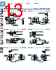
11 / 16 page  405 U-shapedMicroPhotoelectricSensorPM-25SERIES PM-45SERIES PM-65SERIES FIBER SENSORS LASER SENSORS PHOTO- ELECTRIC SENSORS MICRO PHOTO- ELECTRIC SENSORS AREA SENSORS SAFETY LIGHT CURTAINS / SAFETY COMPONENTS PRESSURE / FLOW SENSORS INDUCTIVE PROXIMITY SENSORS PARTICULAR USE SENSORS SENSOR OPTIONS SIMPLE WIRE-SAVING UNITS WIRE-SAVING SYSTEMS MEASURE- MENT SENSORS STATIC CONTROL DEVICES LASER MARKERS PLC HUMAN MACHINE INTERFACES ENERGY MANAGEMENT SOLUTIONS FA COMPONENTS MACHINE VISION SYSTEMS UV CURING SYSTEMS Selection Guide U-shaped Convergent Reflective PM-25/PM-45/ PM-65 PRECAUTIONS FOR PROPER USE Refer to p.1552~ for general precautions. When using the product as an S-mark compatible product in Korea • The power supply cable and output cable connected to the product must be less than 10 m 32.808 ft. Cable extension • Cable extension is possible up to an overall length of 100 m 328.084 ft with a 0.3 mm2, or more, cable. However, since a voltage drop shall occur due to the cable extension, ensure that the power supply voltage at the end of the cable attached to the sensor is within the rating. • Cable extension is possible up to an overall length of 100 m 328.084 ft with a 0.3 mm2, or more, cable. However, since a voltage drop shall occur due to the cable extension, ensure that the power supply voltage at the end of the connector attached cable of the sensor or at the sensor terminals is within the rating. 5 to 24 V DC ±10 % Total cable length 100 m 328.084 ft Supply voltage: 4.5 V or more Cable attached to sensor +V Output 0 V Extension cable + – PM-65 series PM-25 series / PM-45 series Connector attached cableExtension cable Output 5 to 24 V DC ±10 % 0 V +V Total cable length 100 m 328.084 ft Supply voltage: 4.5 V or more + – But, when the overall cable length, including the cable attached to the sensor, is as given below, there is no need to confirm the voltage. Conductor cross-section area of extension cable Total cable length 0.08 to 0.1 mm2 Up to 5 m 16.404 ft 0.2 mm2 Up to 10 m 32.808 ft 0.3 mm2 Up to 20 m 65.617 ft But, when the overall cable length, including the cable attached to the sensor, is as given below, there is no need to confirm the voltage. Conductor cross-section area of extension cable Total cable length 0.08 to 0.1 mm2 Up to 5 m 16.404 ft 0.2 mm2 Up to 10 m 32.808 ft 0.3 mm2 Up to 20 m 65.617 ft Wiring (PM-65 series) Connection method • Insert the connector attached cable CN-14A-C□ / CN-14A-R-C□ in the connector part of this product as shown in the figure below. <Connector> Housing: PAP-04V-S (Manufactured by J.S.T. Mfg. Co., Ltd.) CN-14A-C / CN-14A-R-C Lock release lever <Connector pin position> Connector pin No. Terminal designation +V 0 V Output 1Output 2 Disconnection method • Press and hold the lock release lever to disconnect the cable connector. Note: Pulling the cable without pressing the lock release lever in an attempt to disconnect the connector can cause wire breakage in the cable or damage to the connector. Others • This device has been developed / produced for industrial use only. • Since the sensor is intended for use inside machines, no special countermeasures have been taken against extraneous light. Take care that extraneous light is not directly incident on the beam receiving section. • Do not use during the initial transient time (50 ms) after the power supply is switched on. • Note that the cable of PM-□25-R loses its flexibility when the ambient temperature decreases to about -10 °C +14 °F. • The cable of PM-□25-R is a bending-resistant cable usable on a moving base. When the sensor is mounted on a moving base, secure the sensor cable joint at the unit in place so that stress is not applied to it. • When storing PM-□25-R, make sure that the cable does not come into contact with the sensing section or operation indicator. • If the sensor is used in a place having excessive dust, periodically clean the emitting and receiving sections with a dry, soft cloth. • If there is a large surge generating equipment, such as, motor, solenoid, electromagnetic valve, etc., in the vicinity of the sensor, use a surge absorber on that equipment. Further, do not run the sensor cables along power lines and use a capacitor between +V and 0 V, if required. Use the sensor after confirming that the surge has been eliminated. |
|
|
链接网址 |
| ALLDATASHEET是否为您带来帮助? [ DONATE ] |
关于 Alldatasheet | 广告服务 | 联系我们 | 隐私政策 | 数据表链接 | 链接交换 | 制造商名单 All Rights Reserved©Alldatasheet.com |
| Russian : Alldatasheetru.com | Korean : Alldatasheet.co.kr | Spanish : Alldatasheet.es | French : Alldatasheet.fr | Italian : Alldatasheetit.com Portuguese : Alldatasheetpt.com | Polish : Alldatasheet.pl | Vietnamese : Alldatasheet.vn Indian : Alldatasheet.in | Mexican : Alldatasheet.com.mx | British : Alldatasheet.co.uk | New Zealand : Alldatasheet.co.nz |
|
Family Site : ic2ic.com |
icmetro.com |
 Chinese ▼
 English
 Chinese
 German
 Japanese
 Russian
 Korean
 Spanish
 French
 Italian
 Portuguese
 Polish
 Vietnamese
 Indian
 Mexican
 British
 New Zealand