|
数据搜索系统,热门电子元器件搜索 |
|
|
数据搜索系统,热门电子元器件搜索 |
|
JB2-AAA-R1/A 数据表(PDF) 2 Page - M-System Co.,Ltd. |
|
|
|||||||||||||||||||||||||||||
JB2-AAA-R1/A 数据表(HTML) 2 Page - M-System Co.,Ltd. |
|
|
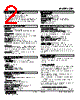
2 / 5 page  MODEL: JB2 JB2 SPECIFICATIONS ES-2642 Rev.5 Page 2/5 http://www.m-system.co.jp/ RELATED PRODUCTS • Programming Unit (model: PU-2x) • PC configurator software (model: JXCON) Downloadable at M-System’s web site. A dedicated cable is required to connect the module to the PC. Please refer to the internet software download site or the users manual for the PC configurator for applicable cable types. GENERAL SPECIFICATIONS Construction: Plug-in Connection: M3.5 screw terminals Screw terminal: Chromated steel (standard) or stainless steel Housing material: Flame-resistant resin (black) Isolation: CAS input or MV output to contact input or power to re-transmitted output to contact output Zero adjustment: -5 to +5 % (front) Span adjustment: 98 to 102 % (front) Indicator LED: RUN output (green), MAN status output (red), UP command (red), DOWN command (red), MAN command (red) Programming: Programming Unit (model: PU-2x); Sliding- back response time, UP-DOWN response time, alarm, etc. (Refer to the users manual of JXCON for the adjustments configurable with JXCON.) Alarm output: RUN contact turns off when the high/low alarm for the CAS input trips. INPUT SPECIFICATIONS ■ CAS Input: 4 – 20 mA DC Input resistance: 25 Ω in manual control mode ■ Contact Input: MAN control command and UP/DOWN command Sensing: 5 V DC @ 3 mA Detection levels ON resistance: ≤ 200 Ω, ≤ 0.80 V OFF resistance: ≥ 100 kΩ, ≥ 4.95 V OUTPUT SPECIFICATIONS ■ MAN Output: 4 – 20 mA DC Load resistance • CAS control mode: Allowable load for CAS signal minus 50 Ω • MAN control mode: 0 – 750 Ω ■ Relay Output: MAN status and RUN output; 120 V AC @ 1 A or 24 V DC @ 1 A Maximum switching voltage: 250 V AC or 30 V DC Maximum switching power: 120 VA or 24 W Minimum load: 5 V DC @100 mA Mechanical life: 2 × 10⁷ cycles INSTALLATION Current consumption CAS mode: Approx. 120 mA at 24 V MAN mode: Approx. 180 mA at 24 V Operating temperature: -5 to +55°C (23 to 131°F) Operating humidity: 30 to 90 %RH (non-condensing) Mounting: Surface or DIN rail Weight: 450 g (0.99 lb) PERFORMANCE in percentage of span Alarm setting accuracy: ±0.5 % Re-transmitted output accuracy: ±0.4 % CAS to MAN or MAN to CAS switching accuracy: ±0.5 % MV output terminal is open during the time switching the internal relay (≤ 10 msec.) when turning CAS to MAN or MAN to CAS mode. Temp. coefficient: ±0.015 %/°C (±0.008 %/°F) Re-transmitted output response time: ≤ 20 msec. Output memory at power OFF: E2PROM (non-volatile memory) Insulation resistance: ≥ 100 MΩ with 500 V DC Dielectric strength: 1000 V AC @ 1 minute (CAS input or MV output to contact input or power to retransmitted output to contact output) 1500 V AC @ 1 minute (CAS input or MV output or contact input or power or re-transmitted output or contact output to ground) OPERATING MODES ■ CASCADE CONTROL MODE The JB2 allows the CAS input (cascade control signal) from the PID controller to pass through at the MV output terminals. ■ MANUAL CONTROL MODE When the external MAN command contact is closed, the JB2 turns on to manual control mode. Actual output signal is determined by following three operation modes: MODE 1: Holds the CAS control signal at the moment of the MAN command. MODE 2: Goes back the preset time period and hold the CAS control signal at that moment. MODE 3: Holds a specific value preset by the Programming Unit (PU-2x). In this mode, the output can be manipulated with external UP or DOWN commands. When the MAN command contact is opened, the CAS control signal is recovered with smooth transition. ■ TRANSITION FROM MAN TO CAS CONTROL MODE The JB2 increases/decreases the MV output until it reaches |
|
|
链接网址 |
| ALLDATASHEET是否为您带来帮助? [ DONATE ] |
关于 Alldatasheet | 广告服务 | 联系我们 | 隐私政策 | 数据表链接 | 链接交换 | 制造商名单 All Rights Reserved©Alldatasheet.com |
| Russian : Alldatasheetru.com | Korean : Alldatasheet.co.kr | Spanish : Alldatasheet.es | French : Alldatasheet.fr | Italian : Alldatasheetit.com Portuguese : Alldatasheetpt.com | Polish : Alldatasheet.pl | Vietnamese : Alldatasheet.vn Indian : Alldatasheet.in | Mexican : Alldatasheet.com.mx | British : Alldatasheet.co.uk | New Zealand : Alldatasheet.co.nz |
|
Family Site : ic2ic.com |
icmetro.com |
 Chinese ▼
 English
 Chinese
 German
 Japanese
 Russian
 Korean
 Spanish
 French
 Italian
 Portuguese
 Polish
 Vietnamese
 Indian
 Mexican
 British
 New Zealand