|
数据搜索系统,热门电子元器件搜索 |
|
|
数据搜索系统,热门电子元器件搜索 |
|
M2XUM-R2V2-R 数据表(PDF) 2 Page - M-System Co.,Ltd. |
|
|
|||||||||||||||||||||||||||||
M2XUM-R2V2-R 数据表(HTML) 2 Page - M-System Co.,Ltd. |
|
|
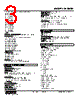
2 / 7 page  MODEL: M2XUM M2XUM SPECIFICATIONS ES-5009 Rev.19 Page 2/7 http://www.m-system.co.jp/ [3] POWER INPUT AC Power M2: 100 – 240 V AC (Operational voltage range 85 – 264 V, 47 – 66 Hz) DC Power R: 24 V DC (Operational voltage range 24 V ±10 %, ripple 10 %p-p max.) P: 110 V DC (Operational voltage range 85 – 150 V, ripple 10 %p-p max.) [4] OPTIONS (multiple selections) Standards & Approvals (must be specified) /N: Without CE /CE: CE marking Other Options blank: none /Q: Option other than the above (specify the specification) SPECIFICATIONS OF OPTION: Q (multiple selections) COATING (For the detail, refer to M-System's web site.) /C01: Silicone coating /C02: Polyurethane coating /C03: Rubber coating TERMINAL SCREW MATERIAL /S01: Stainless steel RELATED PRODUCTS • PC configurator software (model: JXCON) Downloadable at M-System’s web site. A dedicated cable is required to connect the module to the PC. Please refer to the internet software download site or the users manual for the PC configurator for applicable cable types. GENERAL SPECIFICATIONS Construction: Plug-in Connection: M3 screw terminals (torque 0.8 N·m) Screw terminal: Chromated steel (standard) or stainless steel Housing material: Flame-resistant resin (black) Isolation: Input to output to RS-485 to power Overrange output: Approx. -15 to +115 % (Negative current output is not provided.) Manual zero adjustments: -5 to +5 % (factory setting: 0 %) Manual span adjustments: 95 to 105 % (factory setting: 100 %) Programming: PC programmable features include: · T/C and RTD type and temp. range · Input and output ranges · Zero and span adjustments · Simulated output · User's linearization table (max. 100 points, specified within -15 – +115 % for both input and output) · User’s TC/RTD table Burnout (T/C, RTD and Pot.): Upscale standard; downscale or no burnout options are PC programmable Linearization (T/C, RTD input): Standard tables stored in memory Cold junction compensation (T/C): CJC sensor (included) to be attached to the input terminals Status indicator LED: Blinking patterns indicate different operating status of the transmitter. Configurator connection: 2.5 dia. miniature jack; RS-232-C level MODBUS COMMUNICATION Standard: Conforms to TIA/EIA-485-A Transmission distance: 500 meters max. Baud rate: 38.4 kbps max. Communication: Half-duplex, asynchronous, no procedure Protocol: Modbus RTU Transmission media: Shielded twisted-pair cable (CPEV-S 0.9 dia.) INPUT SPECIFICATIONS ■ DC Current: Shunt resistor attached to the input terminals (0.5 W) Operational range: 0 – 70 mA DC with 100 Ω, 0.5 W Input range: 0 – 50 mA DC Minimum span: 2 mA Offset: Lower range can be any specific value within the input range provided that the minimum span is maintained. If not specified, the input range is 4 – 20 mA DC. ■ DC Voltage Operational range: -11.5 – +11.5 V DC Input range: -10 – +10 V DC Minimum span: 10 mV for S1; 100 mV for S2 Offset: Lower range can be any specific value within the input range provided that the minimum span is maintained. If not specified, the input range is shown below. S1: 0 – 100 mV DC S2: 1 – 5 V DC ■ Thermocouple For T/C types K, E, T, B, R, S, N or U, the accuracy in the temperature ranges near the lower limit may be out of the described value. Consult M-System for more detail. Input resistance: 1 MΩ min. Burnout sensing: 45 nA ±10 % Offset: Lower range can be any specific value within the input range provided that the minimum span is maintained. |
|
|
链接网址 |
| ALLDATASHEET是否为您带来帮助? [ DONATE ] |
关于 Alldatasheet | 广告服务 | 联系我们 | 隐私政策 | 数据表链接 | 链接交换 | 制造商名单 All Rights Reserved©Alldatasheet.com |
| Russian : Alldatasheetru.com | Korean : Alldatasheet.co.kr | Spanish : Alldatasheet.es | French : Alldatasheet.fr | Italian : Alldatasheetit.com Portuguese : Alldatasheetpt.com | Polish : Alldatasheet.pl | Vietnamese : Alldatasheet.vn Indian : Alldatasheet.in | Mexican : Alldatasheet.com.mx | British : Alldatasheet.co.uk | New Zealand : Alldatasheet.co.nz |
|
Family Site : ic2ic.com |
icmetro.com |
 Chinese ▼
 English
 Chinese
 German
 Japanese
 Russian
 Korean
 Spanish
 French
 Italian
 Portuguese
 Polish
 Vietnamese
 Indian
 Mexican
 British
 New Zealand