|
数据搜索系统,热门电子元器件搜索 |
|
|
数据搜索系统,热门电子元器件搜索 |
|
R3-NF3-R 数据表(PDF) 3 Page - M-System Co.,Ltd. |
|
|
|||||||||||||||||||||||||||||
R3-NF3-R 数据表(HTML) 3 Page - M-System Co.,Ltd. |
|
|
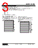
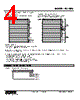
3 / 7 page  MODEL: R3-NF3 R3-NF3 SPECIFICATIONS ES-8288 Rev.2 Page 3/7 http://www.m-system.co.jp/ TRANSMISSION DATA DESCRIPTIONS The DIP SW in the front of the module speci es I/O points, I/O type and with or without of I/O module status data setting. I/O DATA is assigned data allocation setting from module 1 orderly. The data of I/O module out of the setting area is invalid. When there is I/O module status data, use the data area of the last 2 words of the input data area as the status data. When the status data and I/O data overlap, the status data takes precedence. For example, when the number of I/O points is “16” and SW1 and SW2 are set as shown below. Slot 1 4 Slot 2 4 Slot 3 4 Slot 4 1 Slot 5 1 Slot 6 1 Slot 7 1 Then the I/O data are assigned as in the gures below: ■ IN THE CASE OF NO I/O MODULE STATUS (KS3: OFF) • I/O TYPE: INPUT ONLY or OUTPUT ONLY The side DIP SW (SW1, 2) determine data allocation of mod- ule (number of data) per module. The number of data set by SW1 and SW2 is assigned to trans- mission data in order from slot 1. 0 15 +0 +2 +4 +6 +8 +10 +12 +14 Slot 1 Slot 2 Slot 3 Slot 4 Slot 5 Slot 6 Slot 7 Begin Address • I/O TYPE: INPUT / OUTPUT MIXED The number of input points and the number of output points are assigned half numbers of KS0 to 1 respectively. The rst half of the data area is the input area and the second half is the output area. Please set the input module in slot 1 and 2, and output mod- ule after slot 3. 0 15 +0 +2 +4 +6 +8 +10 +12 +14 Slot 1 Slot 2 Slot 3 Slot 4 Slot 5 Slot 6 Slot 7 Input (8 points) Output (8 points) Begin Address |
|
|
链接网址 |
| ALLDATASHEET是否为您带来帮助? [ DONATE ] |
关于 Alldatasheet | 广告服务 | 联系我们 | 隐私政策 | 数据表链接 | 链接交换 | 制造商名单 All Rights Reserved©Alldatasheet.com |
| Russian : Alldatasheetru.com | Korean : Alldatasheet.co.kr | Spanish : Alldatasheet.es | French : Alldatasheet.fr | Italian : Alldatasheetit.com Portuguese : Alldatasheetpt.com | Polish : Alldatasheet.pl | Vietnamese : Alldatasheet.vn Indian : Alldatasheet.in | Mexican : Alldatasheet.com.mx | British : Alldatasheet.co.uk | New Zealand : Alldatasheet.co.nz |
|
Family Site : ic2ic.com |
icmetro.com |
 Chinese ▼
 English
 Chinese
 German
 Japanese
 Russian
 Korean
 Spanish
 French
 Italian
 Portuguese
 Polish
 Vietnamese
 Indian
 Mexican
 British
 New Zealand