|
数据搜索系统,热门电子元器件搜索 |
|
|
数据搜索系统,热门电子元器件搜索 |
|
R7ML-YV2-R 数据表(PDF) 12 Page - M-System Co.,Ltd. |
|
|
|||||||||||||||||||||||||||||
R7ML-YV2-R 数据表(HTML) 12 Page - M-System Co.,Ltd. |
|
|
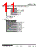
12 / 40 page  MODEL: R7ML http://www.m-system.co.jp/ R7ML SPECIFICATIONS ES-7805 Rev.11 Page 12/40 ■ AUTOMATIC ZERO CORRECTION Set the offset input value. Perform automatic zero correction setting after Zero/Span adjustments. The procedures are as follows. 1) Apply desired offset input value to the sensor. 2) Set “1” to Automatic zero correction bit. When the offset is completed, LED0 for Input 0 or LED8 for Input 1 turns on. 3) After checking the LED, set “0” to Automatic zero correction bit. ■ ZERO ADJUSTMENT Adjust input zero point. The procedures are as follows. 1) Apply 0% load to the sensor. 2) Set “1” to Zero adjustment bit. When the adjustment is completed, LED1 for Input 0 or LED9 for Input 1 turns on. 3) After checking the LED, set “0” to Zero adjustment bit. ■ SPAN ADJUSTMENT (with actual load) Adjust input span point with the actual load. The procedures are as follows. 1) Apply actual 100% load to the sensor. 2) Set “1” to Span adjustment bit. When the adjustment is completed, LED2 for Input 0 or LED10 for Input 1 turns on. 3) After checking the LED, set “0” to Span adjustment bit. ■ LOAD COEFFICIENT Adjust input Span point by setting load coefficient without applying 100% actual load. The followings are an example of adjustment with 20 % load. 1) Apply 20% load of the actual load to the sensor. 2) Set 2000 (decimal) to Input set data area. 3) Set “1” to Span adjustment bit. When the adjustment is completed, LED2 for Input 0 or LED10 for Input 1 turns on. 4) After checking the LED, set “0” to Span adjustment bit. ■ MODE SETTING Select measuring mode or monitor output mode. • Measuring mode Set “0” to Mode setting bit to enter measuring mode. In measuring mode, monitor output is linked with input data. • Monitor output mode Set “1” to Mode setting bit to enter monitor output mode. In monitor output mode, values at set data area of each input are outputted. Set values at set data area are displayed in Input data area and inputs are disabled. The followings are setting procedures of 20% monitor output for Input 1. 1) Set 2000 (decimal) to Input 1 set data area. 2) Set “1” to Mode setting bit. When the setting is completed, LED7 turns on and 20% of Input 1 is outputted from monitor output terminal . 3) After checking the output, set “0” to Mode setting bit to return to measuring mode. ■ RESET OFFSET Reset the offset value set by Automatic zero correction to zero. The procedures are as follows. 1) Set “1” to Reset offset bit. When the reset is completed, LED4 for Input 0 or LED12 for Input 1 turns on. 2) After checking the LED, set “0” to Reset offset bit. “1” is to be set when input is -1.0% or less. ■ INPUT BELOW RANGE (Input only) “1” is to be set when input is within the range between -1.0% and 101.0%. “1” is to be set when input is 101.0% or more. ■ INPUT OVER RANGE (Input only) ■ INPUT WITHIN RANGE (Input only) |
|
链接网址 |
| ALLDATASHEET是否为您带来帮助? [ DONATE ] |
关于 Alldatasheet | 广告服务 | 联系我们 | 隐私政策 | 数据表链接 | 链接交换 | 制造商名单 All Rights Reserved©Alldatasheet.com |
| Russian : Alldatasheetru.com | Korean : Alldatasheet.co.kr | Spanish : Alldatasheet.es | French : Alldatasheet.fr | Italian : Alldatasheetit.com Portuguese : Alldatasheetpt.com | Polish : Alldatasheet.pl | Vietnamese : Alldatasheet.vn Indian : Alldatasheet.in | Mexican : Alldatasheet.com.mx | British : Alldatasheet.co.uk | New Zealand : Alldatasheet.co.nz |
|
Family Site : ic2ic.com |
icmetro.com |
 Chinese ▼
 English
 Chinese
 German
 Japanese
 Russian
 Korean
 Spanish
 French
 Italian
 Portuguese
 Polish
 Vietnamese
 Indian
 Mexican
 British
 New Zealand