|
数据搜索系统,热门电子元器件搜索 |
|
|
数据搜索系统,热门电子元器件搜索 |
|
MAX17552B 数据表(PDF) 2 Page - Maxim Integrated Products |
|
|
|||||||||||||||||||||||||||||
MAX17552B 数据表(HTML) 2 Page - Maxim Integrated Products |
|
|
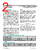
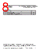
2 / 8 page  Maxim Integrated │ 2 www.maximintegrated.com Evaluates: MAX17552/MAX17552B (TDFN) in 5V Output Voltage Applications MAX17552 5V Output Evaluation Kit (TDFN) Detailed Description The MAX17552 5V EV kit (TDFN) is a fully assembled and tested circuit board that demonstrates the performance of the MAX17552 60V, 100mA ultra-small, high-efficiency, synchronous step-down DC-DC converter in a 10-pin TDFN package. The EV kit operates over a wide input voltage range of 6V to 60V and provides up to 100mA load current at 5V output. It draws only 26µA supply cur- rent under no-load conditions (EN/UVLO connected to VIN). The EV kit is programmed to switch at a frequency of 220kHz and delivers a peak efficiency of 93% with the supplied components. The device is simple to use and easily configurable with minimal external components. It features cycle-by-cycle peak current limit protection, undervoltage lockout, and thermal shutdown. The EV kit includes an EN/UVLO PCB pad and jumpers JU1 and JU2 to enable control of the converter output. The MODE PCB pad and jumper JU3 are provided for selecting the mode of operation of the converter. A RESET PCB pad is available for monitoring the RESET output. The RT/SYNC PCB pad can be used to synchro- nize the EV kit switching frequency to an external clock frequency. Enable Control (JU1, JU2) The EN/UVLO pin on the EV kit serves as an on/off control while also allowing the user to program the input undervolt- age lockout (UVLO) threshold. Jumpers JU1 and JU2 con- figure the EV kit’s output for turn-on/turn-off control. See Table 1 for proper JU1, JU2 jumper configurations. Additionally, resistors R1 and R2 are included to set the UVLO to a desired turn-on voltage. Refer to the Setting the Input Undervoltage-Lockout Level section in the MAX17552 IC data sheet for additional information on setting the UVLO threshold voltage. RESET Output The EV kit provides a PCB pad to monitor the status of the RESET output. RESET goes high and when the out- put voltage rises above 95% (typ) of its nominal regulated output voltage. RESET goes low when output voltage falls below 92% (typ) of its nominal regulated voltage. PFM or Forced-PWM Mode (MODE) The EV kit includes a jumper (JU3) to select the mode of operation of the converter. Install a shunt across JU3 before powering up the EV kit to enable the forced-PWM operation. Keep JU3 open to enable the light-load PFM operation. See Table 2 for proper JU3 settings. Soft-Start The EV kit offers a fixed 5ms soft-start time. Connect the capacitor C4 to adjust the soft-start time (tSS). Use the following equation to determine the soft-start capacitance value (CSS). CSS = 6.25 x tSS where tSS is in milliseconds and CSS is in nanofarads. External Synchronization (RT/SYNC) The EV kit provides a PCB pad to synchronize the EV kit switching frequency to an external clock frequency. Apply the external clock to the RT/SYNC PCB pad though an AC-coupling capacitor. Refer to the External Synchronization section in the MAX17552 IC data sheet for additional information on configuring the external clock and selecting the AC-coupling capacitor. Table 1. Enable Control (EN/UVLO) (JU1, JU2) Table 2. MODE Control (JU3) *Default position. *Default position. SHUNT POSITION EN/UVLO PIN VOUT OUTPUT JU1 JU2 1-2 Open Connected to VIN Enabled Open 1-2 Connected to GND Disabled 1-2* 1-2 Connected to midpoint of R1, R2 resistor-divider Enabled at VIN ≥ 6V SHUNT POSITION MODE PIN MODE OF OPERATION 1-2 Connected to GND Forced PWM Open* Unconnected PFM |
|
|
链接网址 |
| ALLDATASHEET是否为您带来帮助? [ DONATE ] |
关于 Alldatasheet | 广告服务 | 联系我们 | 隐私政策 | 数据表链接 | 链接交换 | 制造商名单 All Rights Reserved©Alldatasheet.com |
| Russian : Alldatasheetru.com | Korean : Alldatasheet.co.kr | Spanish : Alldatasheet.es | French : Alldatasheet.fr | Italian : Alldatasheetit.com Portuguese : Alldatasheetpt.com | Polish : Alldatasheet.pl | Vietnamese : Alldatasheet.vn Indian : Alldatasheet.in | Mexican : Alldatasheet.com.mx | British : Alldatasheet.co.uk | New Zealand : Alldatasheet.co.nz |
|
Family Site : ic2ic.com |
icmetro.com |
 Chinese ▼
 English
 Chinese
 German
 Japanese
 Russian
 Korean
 Spanish
 French
 Italian
 Portuguese
 Polish
 Vietnamese
 Indian
 Mexican
 British
 New Zealand