|
数据搜索系统,热门电子元器件搜索 |
|
|
数据搜索系统,热门电子元器件搜索 |
|
ADR1399 数据表(PDF) 7 Page - Analog Devices |
|
|
|||||||||||||||||||||||||||||
ADR1399 数据表(HTML) 7 Page - Analog Devices |
|
|
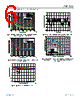
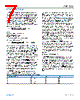
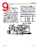
7 / 10 page  Data Sheet ADR1000 THEORY OF OPERATION analog.com Rev. B | 7 of 10 The ADR1000 consists of a buried Zener diode, a temperature compensating transistor, a temperature sensing transistor, and a heater resistor. The output reference voltage (VREF) is formed by summing the buried Zener diode voltage (VBZ1) and a temperature compensating transistor base emitter voltage (VBEQ1), where the Zener diode temperature coefficient is approximately +2 mV/°C, and the transistor VBE temperature coefficient is approximately −2 mV/°C. Referring to Figure 9, an external op amp (U3), in combination with an external resistor (R1), is used to set the Zener operating current as follows: R 1= 0.658 V − 0.0022 × TSET Iz − 7 Ω where: TSET is the heated chip temperature. IZ is the desired Zener current. 0.658 V is the Q1 VBE at 0°C. 7 Ω is the bulk resistance to the Zener anode. With TSET = 70°C and Iz = 4 mA, R 1= 0.658 V − 0.002 × 70 Iz − 7 Ω = 129.5 Ω Note that because the 7 Ω bulk resistance (R0 in Figure 1) sche- matically appears under the Q1 base, it must be included in the calculation of Iz. The primary performance implication of the buried Zener operating current is output voltage noise. The ADR1000 can achieve a total output noise of 0.14 ppm (0.9 µV p-p) in the 0.1 to 10 Hz frequency band when IBZ1 = 5 mA and ICQ1 = 100 µA, with the dominant noise source being the Zener diode. Increasing the current in the Zener (IBZ1) reduces the reference noise by the inverse square root of the Zener current. A Zener bias current greater than 8 mA is not practical because power dissipation limits maximum ambient temperature. The ADR1000 applications circuit output noise spectral density has been measured over a range of Zener set currents (see Figure 3). The ADR1000 long-term drift (LTD) is characterized at a Zener current of IBZ1 = 5 mA and a Q1 current of ICQ1 = 100 µA, and results are shown in Figure 5. SETTING THE OPERATING TEMPERATURE The ADR1000 can regulate chip operating temperature to within a few millidegrees over a 100°C ambient temperature change. This means if the unheated reference temperature coefficient is 20 ppm/°C, then the theoretical heated temperature coefficient is well below 0.1 ppm/°C. This performance is difficult to achieve in a practical circuit (refer to the Avoiding Thermocouple Errors section for more information). The VBE of Q2 is compared to a divided down copy of the 6.62 V reference voltage (see Figure 9). The 13 kΩ:1 kΩ divider sets the VBE of the Q2 at around 474 mV. At room temperature, a VBE of 474 mV does not provide enough collector current to satisfy the condition that the input terminals of U2 must be equal to within a few hundred microvolts. Thus, the noninverting input of U2 is pulled up until its inputs clamp or until its noninverting terminal hits VREF. The voltage difference between the two inputs of U2 causes the output of U2 to pull up, increasing the amount of power dissipated in the on-chip heater. Because the transistor base emitter voltage has a negative temperature coefficient, the collector current of Q2 increases as the chip temperature rises, causing the op amp inputs to move closer together until the voltage drop across R3 satisfies the loop. The temperature at which the thermal loop is satisfied is the chip set temperature (TSET). Figure 7 shows the ADR1000 and LTZ1000A total supply current vs. the ambient temperature. Notice that the heater current has a square root dependence on the difference between the ambient temperature and the set temperature because the power dissipated in the heater is proportional to the square of the current. When the ambient temperature reaches the set temperature, the current in the heater goes to zero, and the chip temperature is no longer regulated. THERMAL RESISTANCE The ADR1000 uses a specialized epoxy die attachment to maxi- mize the thermal isolation that reduces the power consumption required to achieve a given set temperature. At an ambient temper- ature of 10°C, the heater power consumption is approximately 35 mA2 × 242 Ω = 300 mW, assuming that the heater supply current is the total supply current minus 5 mA for the Zener current and other components on the PCB (see Figure 7). For 300 mW dissipation in the heater, the internal temperature of the ADR1000 is elevated by 65°C, yielding a 216°C/W junction to ambient thermal impedance (θJA). Table 6. Recommended Values for Varying the Set Temperature in 5° Increments Estimate Set Temperature (°C) R4 (Ω) R5 (kΩ) VBEQ2 (mV) 80 13 k + 316 1 464 75 13 k 1 474 70 13 k − 316 1 484 65 13 k − 632 1 494 |
|
|
链接网址 |
| ALLDATASHEET是否为您带来帮助? [ DONATE ] |
关于 Alldatasheet | 广告服务 | 联系我们 | 隐私政策 | 数据表链接 | 链接交换 | 制造商名单 All Rights Reserved©Alldatasheet.com |
| Russian : Alldatasheetru.com | Korean : Alldatasheet.co.kr | Spanish : Alldatasheet.es | French : Alldatasheet.fr | Italian : Alldatasheetit.com Portuguese : Alldatasheetpt.com | Polish : Alldatasheet.pl | Vietnamese : Alldatasheet.vn Indian : Alldatasheet.in | Mexican : Alldatasheet.com.mx | British : Alldatasheet.co.uk | New Zealand : Alldatasheet.co.nz |
|
Family Site : ic2ic.com |
icmetro.com |
 Chinese ▼
 English
 Chinese
 German
 Japanese
 Russian
 Korean
 Spanish
 French
 Italian
 Portuguese
 Polish
 Vietnamese
 Indian
 Mexican
 British
 New Zealand