|
数据搜索系统,热门电子元器件搜索 |
|
|
数据搜索系统,热门电子元器件搜索 |
|
20VLP10-R 数据表(PDF) 4 Page - Vishay Siliconix |
|
|
|||||||||||||||||||||||||||||
20VLP10-R 数据表(HTML) 4 Page - Vishay Siliconix |
|
|
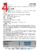
4 / 5 page  20VL Series www.vishay.com Vishay Cera-Mite Revision: 23-Jul-2021 4 Document Number: 23107 For technical questions, contact: ceramitesupport@vishay.com THIS DOCUMENT IS SUBJECT TO CHANGE WITHOUT NOTICE. THE PRODUCTS DESCRIBED HEREIN AND THIS DOCUMENT ARE SUBJECT TO SPECIFIC DISCLAIMERS, SET FORTH AT www.vishay.com/doc?91000 When soldering radial leaded ceramic capacitors with a soldering iron, it should be performed under the following conditions and should not exceed: • Maximum temperature of iron-tip: 400 °C • Maximum soldering iron wattage: 50 W • Maximum soldering time: 3.5 s Failure to follow the above cautions may result, in worst case, in short circuit or cause fuming or thermo-mechanical damage when the product is used. Leaded ceramic capacitors are not designed for reflow process or dipping the body into a solder melt. CLEANING The components should be cleaned immediately following the soldering operation with vapor degreasers. CLEANING (ULTRASONIC CLEANING) To perform ultrasonic cleaning, observe the following conditions: • Maximum rinse bath capacity output: 20 W/liter • Maximum rinsing time: 300 s • Do not vibrate the PCB/PWB directly • Excessive ultrasonic cleaning may lead to mechanical damage SOLVENT RESISTANCE The coating and marking of the capacitors are resistant to the following test method: IEC 60068-2-45 (method XA) MOUNTING We do not recommend modifying the lead terminals, e.g. bending or cropping. This action could break the coating or crack the ceramic insert. In order to avoid such failures we are offering different lead wire designs (e.g. straight, inline, inside crimp, outside crimp etc.) If however, the lead must be modified in any way, we recommend support of the lead with a clamping fixture next to the coating. If a defined product stop is required for mounting on a PCB, a mechanically formed product stop or a mounting tool should be used. OPERATING VOLTAGE In case the voltage is applied to the circuit, starting as well as stopping, may generate irregular voltage for a transit period because of resonance or switching. Be sure to use a capacitor with a rated voltage range that includes these irregular voltages. OPERATING TEMPERATURE AND SELF-GENERATED HEAT Keep the surface temperature of a capacitor below the upper limit of its rated operating temperature range. Be sure to take into account the heat generated by the capacitor itself. When the capacitor is used in a high frequency, pulse, or similar application, it may have self-generated heat due to dielectric dissipation. Temperature increase due to self-generated heating should not exceed 20 °C while operating at an atmosphere temperature of 25 °C. When measuring, the surface temperature, make sure that the capacitor is not affected by radiant, conductive and convective heat by its surroundings. Excessive heat may lead to thermo-mechanical deterioration of the capacitor's characteristics and reliability. RELATED DOCUMENTS General Information www.vishay.com/doc?23140 CB Test Certificate www.vishay.com/doc?22247 VDE Marks Approval www.vishay.com/doc?22246 UL Test Certificate www.vishay.com/doc?22245 |
|
|
链接网址 |
| ALLDATASHEET是否为您带来帮助? [ DONATE ] |
关于 Alldatasheet | 广告服务 | 联系我们 | 隐私政策 | 数据表链接 | 链接交换 | 制造商名单 All Rights Reserved©Alldatasheet.com |
| Russian : Alldatasheetru.com | Korean : Alldatasheet.co.kr | Spanish : Alldatasheet.es | French : Alldatasheet.fr | Italian : Alldatasheetit.com Portuguese : Alldatasheetpt.com | Polish : Alldatasheet.pl | Vietnamese : Alldatasheet.vn Indian : Alldatasheet.in | Mexican : Alldatasheet.com.mx | British : Alldatasheet.co.uk | New Zealand : Alldatasheet.co.nz |
|
Family Site : ic2ic.com |
icmetro.com |
 Chinese ▼
 English
 Chinese
 German
 Japanese
 Russian
 Korean
 Spanish
 French
 Italian
 Portuguese
 Polish
 Vietnamese
 Indian
 Mexican
 British
 New Zealand