|
数据搜索系统,热门电子元器件搜索 |
|
|
数据搜索系统,热门电子元器件搜索 |
|
AD8682ARMZ-R2 数据表(PDF) 11 Page - Analog Devices |
|
|
|||||||||||||||||||||||||||||
AD8682ARMZ-R2 数据表(HTML) 11 Page - Analog Devices |
|
|
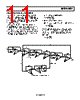
11 / 16 page  AD8682/AD8684 Rev. 0 | Page 11 of 16 PROGRAMMABLE STATE VARIABLE FILTER The circuit shown in Figure 34 can be used to accurately program the Q; the cutoff frequency, fC; and the gain of a 2-pole state variable filter. The AD8684 has been used in this design because of its high bandwidth, low power, and low noise. This circuit takes only three packages to build because of the quad configuration of the op amps and DACs. The DACs shown are used in voltage mode; therefore, many values are dependent on the accuracy of the DAC only and not on the absolute values of the DAC resistive ladders. As a result, this makes the circuit unusually accurate for a programmable filter. Adjusting DAC 1 changes the signal amplitude across R1; therefore, the DAC attenuation × R1 determines the amount of signal current that charges the integrating capacitor, C1. This cutoff frequency can be expressed as ⎟ ⎠ ⎞ ⎜ ⎝ ⎛ = 256 2π 1 D1 R1C1 fc where D1 is the digital code for the DAC. The gain of this circuit is set by adjusting D3. The gain equation is ⎟ ⎠ ⎞ ⎜ ⎝ ⎛ = 256 D3 R5 R4 Gain DAC 2 is used to set the Q of the circuit. Adjusting this DAC controls the amount of feedback from the band-pass node to the input summing node. Note that the digital value of the DAC is in the numerator; therefore, zero code is not a valid operating point. ⎟ ⎠ ⎞ ⎜ ⎝ ⎛ = D2 R3 R2 Q 256 1/4 AD8684 1/4 DAC8408 R5 2kΩ R4 2kΩ 1/4 AD8684 1/4 AD8684 1/4 DAC8408 R1 2kΩ C1 1000pF 1/4 AD8684 1/4 AD8684 1/4 DAC8408 R1 2kΩ C1 1000pF 1/4 AD8684 1/4 DAC8408 R2 2kΩ R3 2kΩ 1/4 AD8684 1/4 AD8684 R6 2kΩ HIGH PASS BAND PASS LOW PASS VIN R7 2kΩ Figure 34. Programmable State Variable Filter |
|
|
链接网址 |
| ALLDATASHEET是否为您带来帮助? [ DONATE ] |
关于 Alldatasheet | 广告服务 | 联系我们 | 隐私政策 | 数据表链接 | 链接交换 | 制造商名单 All Rights Reserved©Alldatasheet.com |
| Russian : Alldatasheetru.com | Korean : Alldatasheet.co.kr | Spanish : Alldatasheet.es | French : Alldatasheet.fr | Italian : Alldatasheetit.com Portuguese : Alldatasheetpt.com | Polish : Alldatasheet.pl | Vietnamese : Alldatasheet.vn Indian : Alldatasheet.in | Mexican : Alldatasheet.com.mx | British : Alldatasheet.co.uk | New Zealand : Alldatasheet.co.nz |
|
Family Site : ic2ic.com |
icmetro.com |
 Chinese ▼
 English
 Chinese
 German
 Japanese
 Russian
 Korean
 Spanish
 French
 Italian
 Portuguese
 Polish
 Vietnamese
 Indian
 Mexican
 British
 New Zealand