|
数据搜索系统,热门电子元器件搜索 |
|
|
数据搜索系统,热门电子元器件搜索 |
|
STV-USB/CIF-R01 数据表(PDF) 50 Page - STMicroelectronics |
|
|
|||||||||||||||||||||||||||||
STV-USB/CIF-R01 数据表(HTML) 50 Page - STMicroelectronics |
|
|
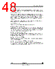
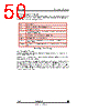
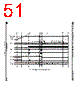
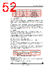
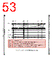
50 / 105 page  VV5410 & VV6410 Digital Video Interface Format cd5410-6410f-3-0.fm Commercial in confidence 50/105 8.8 Power-up, Low-power and Sleep modes Please note that the following descriptions of low power and sleep modes assumes that the user has selected the optional 4 wire output mode, that is D[3:0] will transmit the digital video data. If the 5-wire or 8-wire modes are selected the same basic behaviour is followed however the contents of the data bus will differ slightly. 8.8.1 Power-Up/Down (Figure 29) The sensor enters low-power mode on power-up. On power-up all of the data bus lines are driven high immediately and the device is in low-power mode (Section 8.8.2). The sensor will remain in the low power mode until the external host sends the appropriate message over I2C to clear the low power bit - bit0 of serial reguister, setup0, index 1016. After the “Exit Low-Power Mode” command has been sent the sensor will output for one frame, a continuous stream of alternating 9H and 6H values on D[3:0] The patterns generated in 5 and 8 wire modes are given in Table 16 below. By locking onto the resulting 0101/1010 patterns appearing on the data bus lines the host can determine the best sampling position for the nibble data. After the last 9H 6H pair has been output the data bus returns to FH,(1FH in 5 wire mode), until the start of fifth frame. At this point the first active video frame will be output. After the host has determined the correct sampling position for the data, it should then wait for the next start of frame line (SOF). PU0 System Power Up PU1 Sensor enters low power mode and databus bits driven high. PU2 Host enables the sensor clock, CLKI. PU3-PU4 The host sends a “Soft-Reset” command to the sensor via the serial interface. This ensures that the sensor is in low-power mode. PU5 Host issues command to remove sensor from low-power mode. PU6-PU7 Sensors begins execution 4 frame start sequence. PU8-PU9 One frame of alternating 9H & 6H data on D[3:0] for the host to determine the best sampling phase for video data. PU10-PU11 4 Frames after the “Exit Low-Power Mode” serial comms, the sensor starts outputing valid video data. Table 15 : Typical System Power-Up |
|
链接网址 |
| ALLDATASHEET是否为您带来帮助? [ DONATE ] |
关于 Alldatasheet | 广告服务 | 联系我们 | 隐私政策 | 数据表链接 | 链接交换 | 制造商名单 All Rights Reserved©Alldatasheet.com |
| Russian : Alldatasheetru.com | Korean : Alldatasheet.co.kr | Spanish : Alldatasheet.es | French : Alldatasheet.fr | Italian : Alldatasheetit.com Portuguese : Alldatasheetpt.com | Polish : Alldatasheet.pl | Vietnamese : Alldatasheet.vn Indian : Alldatasheet.in | Mexican : Alldatasheet.com.mx | British : Alldatasheet.co.uk | New Zealand : Alldatasheet.co.nz |
|
Family Site : ic2ic.com |
icmetro.com |
 Chinese ▼
 English
 Chinese
 German
 Japanese
 Russian
 Korean
 Spanish
 French
 Italian
 Portuguese
 Polish
 Vietnamese
 Indian
 Mexican
 British
 New Zealand