|
数据搜索系统,热门电子元器件搜索 |
|
|
数据搜索系统,热门电子元器件搜索 |
|
ADP1653ACPZ-R21 数据表(PDF) 17 Page - Analog Devices |
|
|
|||||||||||||||||||||||||||||
ADP1653ACPZ-R21 数据表(HTML) 17 Page - Analog Devices |
|
|
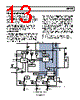
17 / 24 page  ADP1653 Rev. A | Page 17 of 24 APPLICATIONS INFORMATION FLASH-CURRENT FOLDBACK DURING TRANSMIT PULSE The ADP1653 allows a fast, 1.8 V logic-enabled foldback of the flash current, typically enabled shortly before an RF transmit pulse. This feature extends the life of the battery by preventing overstress of the battery cell. It also extends the life of the phone by reducing the maximum instantaneous system current that can occur, allowing a lower battery operating voltage limit. 2-Bit Logic Interface Mode (INTF = 1) In 2-bit logic interface mode, the flash current is set with an external resistor. The 1.22 V reference voltage is buffered to the SETF pin, generating a reference current across an external SETF resistor. This reference current is multiplied by a fixed gain to set the flash current in the HPLED. A 1.8 V compatible logic signal selects normal or reduced flash current by adjusting the reference current, as shown in Figure 29 and Figure 30. SETF 1.22V 1.22V R1 R2 IREF 1.22V/R1 1.22V/R2 CURRENT MIRRORS DIGITAL OUTPUT TxMASK = 0V Figure 29. Flash Mode Current Foldback (Normal Operation with R2 Grounded Through Digital Control Signal) Full-current flash mode has a reference current of R2 R1 R2 R1 R2 R1 I 0 REF × + × = = ) ( V 22 . 1 // V 22 . 1 _ (6) The reference current is multiplied by a fixed gain to give the actual flash current (see Table 8). SETF 1.22V 1.22V R1 R2 IREF 1.22V/R1 0.6V/R2 CURRENT MIRRORS DIGITAL OUTPUT TxMASK = 1.8V 1.8V Figure 30. Flash Mode Current Foldback with 1.8 V Signal Applied to R2 A logic high to R2 changes the direction of the current in R2. IREF = IR1 − IR2 (7) R2 V R1 I mask Tx REF V 22 . 1 V 22 . 1 − − = (8) IHPLED = IREF × 20,800 (9) The ratio of full flash current to reduced flash current for a 1.8 V logic signal is approximately 2 R1 R2 R1 R2 Flash Reduced Flash Full − + = (10) If R1 = R2 = 100 kΩ, maximum flash current is 500 mA, and reduced flash current is 125 mA. I2C Mode (INTF = 0) To allow flash current foldback in I2C mode, the user should connect a resistor between SETF and ground, and another resistor from SETF to the logic input, as shown in Figure 29 and Figure 30. Operation is the same as for the 2-bit logic interface mode, except the flash current is additionally scaled by setting the HPLED bits in the OUT_SEL register. Full-current flash mode (Tx mask = 0 V) has a flash current of SETF HPLED R Code I kΩ 50 mA) 15 mA 35 ( × × + = (11) where: RSETF is a parallel combination of R1 and R2. Code is the HPLED register setting. Bring the Tx mask voltage high for reduced reference current. Therefore, the reduced LED current is IHPLED (see Equation 13). R2 V R1 I mask Tx REF V 22 . 1 V 22 . 1 − − = (12) V 22 . 1 kΩ 50 mA) 15 mA 35 ( REF HPLED I Code I × × × + = (13) |
|
|
链接网址 |
| ALLDATASHEET是否为您带来帮助? [ DONATE ] |
关于 Alldatasheet | 广告服务 | 联系我们 | 隐私政策 | 数据表链接 | 链接交换 | 制造商名单 All Rights Reserved©Alldatasheet.com |
| Russian : Alldatasheetru.com | Korean : Alldatasheet.co.kr | Spanish : Alldatasheet.es | French : Alldatasheet.fr | Italian : Alldatasheetit.com Portuguese : Alldatasheetpt.com | Polish : Alldatasheet.pl | Vietnamese : Alldatasheet.vn Indian : Alldatasheet.in | Mexican : Alldatasheet.com.mx | British : Alldatasheet.co.uk | New Zealand : Alldatasheet.co.nz |
|
Family Site : ic2ic.com |
icmetro.com |
 Chinese ▼
 English
 Chinese
 German
 Japanese
 Russian
 Korean
 Spanish
 French
 Italian
 Portuguese
 Polish
 Vietnamese
 Indian
 Mexican
 British
 New Zealand