|
数据搜索系统,热门电子元器件搜索 |
|
|
数据搜索系统,热门电子元器件搜索 |
|
AD8148ACPZ-R2 数据表(PDF) 17 Page - Analog Devices |
|
|
|||||||||||||||||||||||||||||
AD8148ACPZ-R2 数据表(HTML) 17 Page - Analog Devices |
|
|
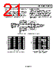
17 / 24 page  AD8146/AD8147/AD8148 Rev. 0 | Page 17 of 24 –OUT R +OUT R –OUT G +OUT G –OUT B +OUT B VOCM WEIGHTING EQUATIONS: RED VOCM = K(VSYNC – HSYNC) + VMIDSUPPLY GREEN VOCM = K(–2VSYNC) + VMIDSUPPLY BLUE VOCM = K(VSYNC + HSYNC) + VMIDSUPPLY +IN R –IN R VSYNC HSYNC SYNC LEVEL +IN G –IN G +IN B –IN B R 1kΩ 1kΩ AD8147/AD8148 500Ω 500Ω G 1kΩ 1kΩ 500Ω 500Ω VOCM VOCM VOCM B 1kΩ 1kΩ 500Ω 500Ω OPD ×2 2 2 2 Figure 30. AD8147/AD8148 Sync-On Common-Mode Encoding Scheme 0 0.5 1.0 1.5 2.0 4.0 3.5 4.5 2.5 3.0 5.0 0.98 0.99 1.00 1.01 1.03 1.04 1.05 1.02 1.06 1.07 TIME (µs) HSYNC VSYNC 2.0 2.1 2.2 2.3 2.4 2.9 2.8 3.0 2.5 2.6 2.7 3.1 R G B Figure 31. AD8147 Sync-On Common-Mode Signals in Single 5 V Application The transmitted common-mode sync signal magnitudes are scaled by applying a dc voltage to the SYNC LEVEL input, referenced to GND. The difference between the voltage applied to the SYNC LEVEL input and GND sets the peak deviation of the encoded sync signals about the midsupply, common-mode voltage. For example, with the SYNC LEVEL input set at 500 mV, the deviation of the encoded sync pulses about the nominal midsupply, common-mode voltage is typically ±500 mV. The equations in Figure 30 describe how the VSYNC and HSYNC signals are encoded on each color’s midsupply common-mode signal. In these equations, the weights of the VSYNC and HSYNC signals are ±1 (+1 for high and −1 for low), and the constant K is equal to the peak deviation of the encoded sync signals. Figure 31 shows how the sync signals appear on each common- mode voltage in a single 5 V supply application when the voltage applied to the SYNC LEVEL input is 500 mV, which is the typical setting for most applications. |
|
|
链接网址 |
| ALLDATASHEET是否为您带来帮助? [ DONATE ] |
关于 Alldatasheet | 广告服务 | 联系我们 | 隐私政策 | 数据表链接 | 链接交换 | 制造商名单 All Rights Reserved©Alldatasheet.com |
| Russian : Alldatasheetru.com | Korean : Alldatasheet.co.kr | Spanish : Alldatasheet.es | French : Alldatasheet.fr | Italian : Alldatasheetit.com Portuguese : Alldatasheetpt.com | Polish : Alldatasheet.pl | Vietnamese : Alldatasheet.vn Indian : Alldatasheet.in | Mexican : Alldatasheet.com.mx | British : Alldatasheet.co.uk | New Zealand : Alldatasheet.co.nz |
|
Family Site : ic2ic.com |
icmetro.com |
 Chinese ▼
 English
 Chinese
 German
 Japanese
 Russian
 Korean
 Spanish
 French
 Italian
 Portuguese
 Polish
 Vietnamese
 Indian
 Mexican
 British
 New Zealand