|
数据搜索系统,热门电子元器件搜索 |
|
|
数据搜索系统,热门电子元器件搜索 |
|
LTC2913IDD-2 数据表(PDF) 7 Page - Linear Technology |
|
|
|||||||||||||||||||||||||||||
LTC2913IDD-2 数据表(HTML) 7 Page - Linear Technology |
|
|
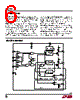
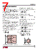
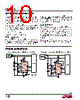
7 / 12 page  LTC2913 7 2913fa APPLICATIONS INFORMATION Voltage Monitoring The LTC2913 is a low power dual voltage monitoring circuit with two undervoltage and two overvoltage inputs. A timeout period that holds OV and UV asserted after all faultshaveclearedisadjustableusinganexternalcapacitor and is externally disabled. Each voltage monitor has two inputs (VHn and VLn) for detecting undervoltage and overvoltage conditions. When configured to monitor a positive voltage Vn using the 3-resistor circuit configuration shown in Figure 1, VHn is connected to the high side tap of the resistive divider and VLn is connected to the low side tap of the resistive divider. 3-Step Design Procedure The following 3-step design procedure determines ap- propriate resistances to obtain the desired UV and OV trip points for the voltage monitor circuit in Figure 1. For supply monitoring, Vn is the desired nominal operat- ing voltage, In is the desired nominal current through the resistive divider, VOV is the desired overvoltage trip point and VUV is the desired undervoltage trip point. 1. Choose RA to obtain the desired OV trip point RA is chosen to set the desired trip point for the overvoltage monitor. R V I V V A n n OV = 0 5 . • (1) 2. Choose RB to obtain the desired UV trip point Once RA is known, RB is chosen to set the desired trip point for the undervoltage monitor. R V I V V R B n n UV A = 0 5 . • – (2) 3. Choose RC to complete the design Once, RA and RB are known, RC is determined by: R V I R R C n n A B = – – (3) If any of the variables Vn, In, VUV or VOV change, then each step must be recalculated. Voltage Monitor Example A typical voltage monitor application is shown in Figure 2. The monitored voltage is a 5V ±10% supply. Nominal cur- rent in the resistive divider is 10µA. 1. Find RA to set the OV trip point of the monitor. R V µA V V k A = ≈ 0 5 10 5 5 5 45 3 . • . . 2. Find RB to set the UV trip point of the monitor. R V µA V V k k B = ≅ 0 5 10 5 4 5 45 3 10 2 . • . – . . 3. Determine RC to complete the design. R V µA k k k C = − ≈ 5 10 45 3 10 2 442 – . . +– 0.5V LTC2913 UVn VHn RC RB RA 2913 F01 Vn VLn OVn Figure 1. 3-Resistor Positive UV/OV Monitoring Configuration VH1 RC 442k RB 10.2k RA 45.3k VCC GND LTC2913 VL1 2913 F02 OV UV VCC 5V V1 5V ±10% Figure 2. Typical Supply Monitor |
|
|
链接网址 |
| ALLDATASHEET是否为您带来帮助? [ DONATE ] |
关于 Alldatasheet | 广告服务 | 联系我们 | 隐私政策 | 数据表链接 | 链接交换 | 制造商名单 All Rights Reserved©Alldatasheet.com |
| Russian : Alldatasheetru.com | Korean : Alldatasheet.co.kr | Spanish : Alldatasheet.es | French : Alldatasheet.fr | Italian : Alldatasheetit.com Portuguese : Alldatasheetpt.com | Polish : Alldatasheet.pl | Vietnamese : Alldatasheet.vn Indian : Alldatasheet.in | Mexican : Alldatasheet.com.mx | British : Alldatasheet.co.uk | New Zealand : Alldatasheet.co.nz |
|
Family Site : ic2ic.com |
icmetro.com |
 Chinese ▼
 English
 Chinese
 German
 Japanese
 Russian
 Korean
 Spanish
 French
 Italian
 Portuguese
 Polish
 Vietnamese
 Indian
 Mexican
 British
 New Zealand