|
数据搜索系统,热门电子元器件搜索 |
|
|
数据搜索系统,热门电子元器件搜索 |
|
AD736BRZ-R7 数据表(PDF) 15 Page - Analog Devices |
|
|
|||||||||||||||||||||||||||||
AD736BRZ-R7 数据表(HTML) 15 Page - Analog Devices |
|
|
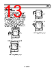
15 / 20 page  Data Sheet AD736 Rev. I | Page 15 of 20 ADDITIONAL APPLICATION CONCEPTS Figure 25 through Figure 28 show four application concepts. Figure 25 shows the high input impedance FET input connected to a multitap attenuator network used in various types of instruments requiring wide ranges of voltages. For a direct network connection, the gate-charge bleeding resistor is not required. The impedance of the FET input is high enough (1012 Ω) so that the loading error is negligible. Manufacturers and distributors of the matched precision resistor networks shown in these figures can easily be found on the Web. The voltages shown in the diagrams are the input levels corresponding to 200 mV at each tap. Finally, the 47 kΩ, 1 W resistor and diode pair are a practical input protection scheme for ac line connection measurements. Figure 26 shows both inputs connected differentially. Figure 27 shows additional components used for offset correction of the output amplifier, and Figure 28 shows connections for single- supply operation such as is the case for handheld devices. Further information can be found in the AN-268 Application Note—RMS-to-DC Converters Ease Measurement Tasks—and the RMS to DC Converter Application Guide, both of which can be found on the Analog Devices, Inc., website. +VS +VS CAV 33µF 47kΩ 1W CC 10µF COM (OPTIONAL) OUTPUT 8 7 6 5 1 2 3 4 AD736 + rms CORE + CC VIN FULL WAVE RECTIFIER CF –VS –VS +VS –VS CAV BIAS SECTION INPUT AMPLIFIER 8kΩ OUTPUT AMPLIFIER 8kΩ CF 10µF 1µF 1µF (OPTIONAL) + OPTIONAL AC COUPLING CAPACITOR VIN FOR FULL SCALE OUTPUT 0.01µF 1kV 2V 20V 200V 9MΩ 900kΩ 90kΩ 10kΩ VIN 200mV BAV199 Figure 25. AD736 with a High Impedance Input Attenuator +VS +VS CAV 33µF COM OUTPUT OUTPUT 8 7 6 5 1 2 3 4 AD736 + rms CORE CC VIN FULL WAVE RECTIFIER CF –VS –VS CAV BIAS SECTION INPUT AMPLIFIER 8kΩ OUTPUT AMPLIFIER 8kΩ CF 10µF CC 10µF 1µF 1µF (OPTIONAL) + +IN INPUT IMPEDANCE: 1012 Ω||10pF –IN AD711 + 3 2 6 Figure 26. Differential Input Connection |
|
|
链接网址 |
| ALLDATASHEET是否为您带来帮助? [ DONATE ] |
关于 Alldatasheet | 广告服务 | 联系我们 | 隐私政策 | 数据表链接 | 链接交换 | 制造商名单 All Rights Reserved©Alldatasheet.com |
| Russian : Alldatasheetru.com | Korean : Alldatasheet.co.kr | Spanish : Alldatasheet.es | French : Alldatasheet.fr | Italian : Alldatasheetit.com Portuguese : Alldatasheetpt.com | Polish : Alldatasheet.pl | Vietnamese : Alldatasheet.vn Indian : Alldatasheet.in | Mexican : Alldatasheet.com.mx | British : Alldatasheet.co.uk | New Zealand : Alldatasheet.co.nz |
|
Family Site : ic2ic.com |
icmetro.com |
 Chinese ▼
 English
 Chinese
 German
 Japanese
 Russian
 Korean
 Spanish
 French
 Italian
 Portuguese
 Polish
 Vietnamese
 Indian
 Mexican
 British
 New Zealand