|
数据搜索系统,热门电子元器件搜索 |
|
|
数据搜索系统,热门电子元器件搜索 |
|
AD8065WARTZ-R7 数据表(PDF) 23 Page - Analog Devices |
|
|
|||||||||||||||||||||||||||||
AD8065WARTZ-R7 数据表(HTML) 23 Page - Analog Devices |
|
|
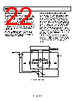
23 / 28 page  Data Sheet AD8065/AD8066 Rev. L | Page 23 of 28 LAYOUT, GROUNDING, AND BYPASSING CONSIDERATIONS POWER SUPPLY BYPASSING Power supply pins are actually inputs and care must be taken so that a noise-free stable dc voltage is applied. The purpose of bypass capacitors is to create low impedances from the supply to ground at all frequencies, thereby shunting or filtering most of the noise. Decoupling schemes are designed to minimize the bypassing impedance at all frequencies with a parallel combination of capacitors. 0.1 µF (X7R or NPO) chip capacitors are critical and should be as close as possible to the amplifier package. The 4.7 µF tantalum capacitor is less critical for high frequency bypassing, and, in most cases, only one is needed per board at the supply inputs. GROUNDING A ground plane layer is important in densely packed PC boards to spread the current minimizing parasitic inductances. However, an understanding of where the current flows in a circuit is critical to implementing effective high speed circuit design. The length of the current path is directly proportional to the magnitude of parasitic inductances and, therefore, the high frequency impedance of the path. High speed currents in an inductive ground return create unwanted voltage noise. The length of the high frequency bypass capacitor leads is most critical. A parasitic inductance in the bypass grounding works against the low impedance created by the bypass capacitor. Place the ground leads of the bypass capacitors at the same physical location. Because load currents flow from the supplies as well, the ground for the load impedance should be at the same physical location as the bypass capacitor grounds. For the larger value capacitors, which are effective at lower frequencies, the current return path distance is less critical. LEAKAGE CURRENTS Poor PC board layout, contaminants, and the board insulator material can create leakage currents that are much larger than the input bias current of the AD8065/AD8066. Any voltage differential between the inputs and nearby runs sets up leakage currents through the PC board insulator, for example, 1 V/100 GΩ = 10 pA. Similarly, any contaminants on the board can create significant leakage (skin oils are a common problem). To reduce leakage significantly, put a guard ring (shield) around the inputs and input leads that are driven to the same voltage potential as the inputs. This way there is no voltage potential between the inputs and surrounding area to set up any leakage currents. For the guard ring to be completely effective, it must be driven by a relatively low impedance source and should completely surround the input leads on all sides, above and below, using a multilayer board. Another effect that can cause leakage currents is the charge absorption of the insulator material itself. Minimizing the amount of material between the input leads and the guard ring helps to reduce the absorption. Also, low absorption materials, such as Teflon® or ceramic, could be necessary in some instances. INPUT CAPACITANCE Along with bypassing and ground, high speed amplifiers can be sensitive to parasitic capacitance between the inputs and ground. A few pF of capacitance reduces the input impedance at high frequencies, in turn increasing the amplifier’s gain, causing peaking of the frequency response or even oscillations, if severe enough. It is recommended that the external passive components connected to the input pins be placed as close as possible to the inputs to avoid parasitic capacitance. The ground and power planes must be kept at a small distance from the input pins on all layers of the board. OUTPUT CAPACITANCE To a lesser extent, parasitic capacitances on the output can cause peaking and ringing of the frequency response. There are two methods to effectively minimize their effect: • As shown in Figure 57, put a small value resistor (RS) in series with the output to isolate the load capacitor from the amp’s output stage. A good value to choose is 20 Ω (see Figure 10). • Increase the phase margin with higher noise gains or add a pole with a parallel resistor and capacitor from −IN to the output. RS = 20Ω VI AD8065 CL VO Figure 57. Output Isolation Resistor |
|
|
链接网址 |
| ALLDATASHEET是否为您带来帮助? [ DONATE ] |
关于 Alldatasheet | 广告服务 | 联系我们 | 隐私政策 | 数据表链接 | 链接交换 | 制造商名单 All Rights Reserved©Alldatasheet.com |
| Russian : Alldatasheetru.com | Korean : Alldatasheet.co.kr | Spanish : Alldatasheet.es | French : Alldatasheet.fr | Italian : Alldatasheetit.com Portuguese : Alldatasheetpt.com | Polish : Alldatasheet.pl | Vietnamese : Alldatasheet.vn Indian : Alldatasheet.in | Mexican : Alldatasheet.com.mx | British : Alldatasheet.co.uk | New Zealand : Alldatasheet.co.nz |
|
Family Site : ic2ic.com |
icmetro.com |
 Chinese ▼
 English
 Chinese
 German
 Japanese
 Russian
 Korean
 Spanish
 French
 Italian
 Portuguese
 Polish
 Vietnamese
 Indian
 Mexican
 British
 New Zealand