|
数据搜索系统,热门电子元器件搜索 |
|
|
数据搜索系统,热门电子元器件搜索 |
|
ADL5519ACPZ-R7 数据表(PDF) 26 Page - Analog Devices |
|
|
|||||||||||||||||||||||||||||
ADL5519ACPZ-R7 数据表(HTML) 26 Page - Analog Devices |
|
|
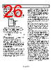
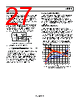
26 / 39 page  ADL5519 Data Sheet Rev. C | Page 26 of 39 ALTERING THE SLOPE As discussed in the Setpoint Interface—VSTA, VSTB section, the slope can readily be increased by scaling the amount of output voltage at OUTA, OUTB that is fed back to the setpoint interface, VSTA, VSTB. When the full signal from OUTA, OUTB is applied to VSTA, VSTB, the slope has a nominal value of −22 mV/dB. This value can be increased by including a voltage divider between the OUTA, OUTB and VSTA, VSTB pins, as shown in Figure 64. ADL5519 OUTA, OUTB VOUT R1 R2 VSTA, VSTB Figure 64. External Network to Raise Slope The approximate input resistance for VSTA, VSTB is 40 kΩ. Scaling resistor values should be carefully selected to minimize errors. Keep in mind that these resistors also load the output pins and reduce the load-driving capabilities. Equation 11 can be used to calculate the resistor values. 1 22 D S R2' R1 (11) where: SD is the desired slope, expressed in millivolts/decibels (mV/dB). R2' is the value of R2 in parallel with 40 kΩ. For example, using R1 = 1.65 kΩ and R2 = 1.69 kΩ (R2' = 1.62 kΩ), the nominal slope is increased to −44 mV/dB. When the slope is increased, the loop capacitor, CLPA, CLPB, may need to be raised to ensure stability and to preserve a chosen averaging time. The slope can be lowered by placing a voltage divider after the output pin, following standard practices. CHANNEL ISOLATION Isolation must be considered when using both channels of the ADL5519 at the same time. The two isolation requirements that should be considered are the isolation from one RF channel input to the other RF channel input and the isolation from one RF channel input to the other channel output. When using both channels of the ADL5519, care should be taken in the layout to isolate the RF inputs, INHA and INHB, from each other. Coupling on the PC board affects both types of isolation. In most applications, the designer has the ability to adjust the power going into the ADL5519 through the use of temperature- stable couplers and accurate temperature-stable attenuators of different values. When isolation is a concern, it is useful to adjust the input power so the lowest expected detectable power is not far from the lowest detectable power of the ADL5519 at the frequency of operation. The lowest detectable power point of the ADL5519 has little variation from part to part. This equalizes the signals on both channels at their lowest possible power level, which reduces the overall isolation requirements and possibly adds attenuators to the RF inputs of the device, reducing the RF channel input isolation requirements. Measuring the RF channel input to the other RF channel input isolation is straightforward and is done by measuring the loss on a network analyzer from one input to the other input. The outcome is shown in the Specifications section of the data sheet. Note that adding an attenuator in series with the RF signal increases the channel input-to-input isolation by the value of the attenuator. The isolation between one RF channel input and the other channel output is a little more complicated. The easiest approach (which was used in this datasheet) to measuring this isolation is to have one channel set to the lowest power level it is expected to have on its input (approximately −50 dBm in this data sheet) and then increasing the power level on the other channel input until the output of the low power channel changes by 22 mV. Because −50 dBm is in the linear region of the detector, 22 mV equates to a 1 dB change in the output. If the inputs to both RF channels are at the same frequency, the isolation also depends on the phase shift between the RF signals put into the ADL5519. This relationship can be demonstrated by placing a high power signal on one RF channel input and a low power signal slightly offset in frequency to the other RF channel. If the output of the low power channel is observed with an oscilloscope, it has a ripple that looks similar to a full-wave rectified sine wave with a frequency equal to the frequency difference between the two channels, that is, a beat tone. The magnitude of the ripple reflects the isolation at a specific phase offset (note that two signals of slightly different frequencies act like two signals with a constantly changing phase), and the frequency of that ripple is directly related to the frequency offset. The data shown in the Specifications section assumes worst-case amplitude and phase offset. If the RF signals on Channel A and Channel B are at significantly different frequencies, the input- to-output isolation increases, depending on the capacitors placed on CLPA, CLPB and the frequency offset of the two signals, due to the response roll-off within the ADL5519. |
|
链接网址 |
| ALLDATASHEET是否为您带来帮助? [ DONATE ] |
关于 Alldatasheet | 广告服务 | 联系我们 | 隐私政策 | 数据表链接 | 链接交换 | 制造商名单 All Rights Reserved©Alldatasheet.com |
| Russian : Alldatasheetru.com | Korean : Alldatasheet.co.kr | Spanish : Alldatasheet.es | French : Alldatasheet.fr | Italian : Alldatasheetit.com Portuguese : Alldatasheetpt.com | Polish : Alldatasheet.pl | Vietnamese : Alldatasheet.vn Indian : Alldatasheet.in | Mexican : Alldatasheet.com.mx | British : Alldatasheet.co.uk | New Zealand : Alldatasheet.co.nz |
|
Family Site : ic2ic.com |
icmetro.com |
 Chinese ▼
 English
 Chinese
 German
 Japanese
 Russian
 Korean
 Spanish
 French
 Italian
 Portuguese
 Polish
 Vietnamese
 Indian
 Mexican
 British
 New Zealand