|
数据搜索系统,热门电子元器件搜索 |
|
|
数据搜索系统,热门电子元器件搜索 |
|
AD8317ACPZ-R7 数据表(PDF) 14 Page - Analog Devices |
|
|
|||||||||||||||||||||||||||||
AD8317ACPZ-R7 数据表(HTML) 14 Page - Analog Devices |
|
|
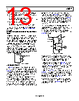
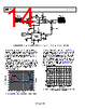
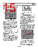
14 / 19 page  AD8317 Data Sheet Rev. D | Page 14 of 19 INLO INHI GAIN OPLO OPHI DIRECTIONAL COUPLER ATTENUATOR VPSx COMx ADL5330 +5V +5V +5V COMM VOUT VPOS VSET INHI INLO CLPF AD8317 LOG AMP DAC RF OUTPUT SIGNAL 4.12kΩ 10kΩ SETPOINT VOLTAGE 1nF 47nF 47nF 120nH 120nH 100pF 100pF 100pF 100pF TADJ 18kΩ 52.3Ω RF INPUT SIGNAL Figure 30. AD8317 Operating in Controller Mode to Provide Automatic Gain Control Functionality in Combination with the ADL5330 Figure 31 shows the transfer function of the output power vs. the setpoint voltage over temperature for a 900 MHz sine wave with an input power of −1.5 dBm. Note that the power control of the AD8317 has a negative sense. Decreasing VSET, which corresponds to demanding a higher signal from the ADL5330, increases gain. The AGC loop is capable of controlling signals just under the full 60 dB gain control range of the ADL5330. The performance over temperature is most accurate over the highest power range, where it is generally most critical. Across the top 40 dB range of output power, the linear conformance error is well within ±0.5 dB over temperature. –50 –40 –30 –10 0 10 20 30 –20 –4 –3 0 1 2 3 4 –1 –2 0.2 0.4 0.6 0.8 1.0 1.4 1.8 2.0 SETPOINT VOLTAGE (V) 1.6 1.2 Figure 31. ADL5330 Output Power vs. AD8317 Setpoint Voltage, PIN = −1.5 dBm For the AGC loop to remain in equilibrium, the AD8317 must track the envelope of the ADL5330 output signal and provide the necessary voltage levels to the ADL5330 gain control input. Figure 32 shows an oscilloscope screenshot of the AGC loop depicted in Figure 30. A 100 MHz sine wave with 50% AM modulation is applied to the ADL5330. The output signal from the VGA is a constant envelope sine wave with amplitude corre- sponding to a setpoint voltage at the AD8317 of 1.5 V. Also shown is the gain control response of the AD8317 to the changing input envelope. CH1 200mV CH3 50.0mVΩ A CH2 820mV M2.00ms T 640.00µs 1 3 2 AM MODULATED INPUT AD8317 OUTPUT ADL5330 OUTPUT Ch2 200mV Figure 32. Oscilloscope Screenshot Showing an AM Modulated Input Signal and the Response from the AD8317 |
|
|
链接网址 |
| ALLDATASHEET是否为您带来帮助? [ DONATE ] |
关于 Alldatasheet | 广告服务 | 联系我们 | 隐私政策 | 数据表链接 | 链接交换 | 制造商名单 All Rights Reserved©Alldatasheet.com |
| Russian : Alldatasheetru.com | Korean : Alldatasheet.co.kr | Spanish : Alldatasheet.es | French : Alldatasheet.fr | Italian : Alldatasheetit.com Portuguese : Alldatasheetpt.com | Polish : Alldatasheet.pl | Vietnamese : Alldatasheet.vn Indian : Alldatasheet.in | Mexican : Alldatasheet.com.mx | British : Alldatasheet.co.uk | New Zealand : Alldatasheet.co.nz |
|
Family Site : ic2ic.com |
icmetro.com |
 Chinese ▼
 English
 Chinese
 German
 Japanese
 Russian
 Korean
 Spanish
 French
 Italian
 Portuguese
 Polish
 Vietnamese
 Indian
 Mexican
 British
 New Zealand