|
数据搜索系统,热门电子元器件搜索 |
|
|
数据搜索系统,热门电子元器件搜索 |
|
HFBR-RLS500Z 数据表(PDF) 5 Page - AVAGO TECHNOLOGIES LIMITED |
|
|
|||||||||||||||||||||||||||||
HFBR-RLS500Z 数据表(HTML) 5 Page - AVAGO TECHNOLOGIES LIMITED |
|
|
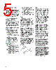
5 / 11 page  5 Step-by-Step Plastic Cable Connectoring Instructions The following step-by-step guide describes how to terminate plastic fiber optic cable. It is ideal for both field and factory installation. Connectors can be easily installed on cable ends with wire strippers, cutters and a crimping tool. Finishing the cable is accom- plished with the Avago HFBR-4593Z Polishing Kit, consisting of a Polishing Fixture, 600 grit abrasive paper and 3 µm pink lapping film (3M Company, OC3-14). The connector can be used immediately after polishing. Materials needed for plastic fiber termination are: 1. Avago Plastic Optical Fiber Cable (Example: HFBR- RUS500Z, HFBR-RUD500Z, HFBR-EUS500Z, or HFBR- EUD500Z) 2. Industrial Razor Blade or Wire Cutters 3. 16 Gauge Latching Wire Strippers (Example: Ideal StripmasterTM type 45-092). 4. HFBR-4597Z Crimping Tool 5. HFBR-4593Z Polishing Kit 6. One of the following connectors: a) HFBR-4501Z/4503Z Gray Simplex/Simplex Latching Connector and HFBR-4525Z Simplex Crimp Ring b) HFBR-4511Z/4513Z Blue Simplex/Simplex Latching Connector and HFBR-4525Z Simplex Crimp Ring c) HFBR-4506Z Parchment (off-white) Duplex Connector and HFBR-4526Z Duplex Crimp Ring d) HFBR-4516Z Gray Latching Duplex Connector and HFBR-4526Z Duplex Crimp Ring Step 1 The zip cord structure of the duplex cable permits easy separation of the channels. The channels should be separated a minimum of 100 mm (4 in) to a maximum of 150 mm (6 in) back from the ends to permit connectoring and polishing. After cutting the cable to the desired length, strip off approxi- mately 7 mm (0.3 in.) of the outer jacket with the 16 gauge wire strippers. Excess webbing on the duplex cable may have to be trimmed to allow the simplex or simplex latching connector to slide over the cable. When using the duplex connector and duplex cable, the separated duplex cable must be stripped to equal lengths on each cable. This allows easy and proper seating of the cable into the duplex connector. Step 2 Place the crimp ring and connec- tor over the end of the cable; the fiber should protrude about 3 mm (0.12 in.) through the end of the connector. Carefully position the ring so that it is entirely on the connector with the rim of the crimp ring flush with the connec- tor, leaving a small space between the crimp ring and the flange. Then crimp the ring in place with the crimping tool. One crimp tool is used for all POF connector crimping requirements. For applications with extreme temperature operation or frequent temperature cycling, improved connector to cable attachment can be achieved with the use of an RTV (GE Company, RTV-128 or Dow Corning 3145-RTV) adhesive. The RTV is placed into the connector prior to insertion of the fiber and the fiber is crimped normally. The connector can be polished after the RTV has cured and is then ready for use. Note: By convention, place the gray connector on the trans- mitter cable end and the blue connector on the receiver cable end to maintain color coding (different color connectors are mechanically identical). Simplex connector crimp rings cannot be used with duplex con- nectors and duplex connector crimp rings cannot be used with simplex connectors because of size differences. The simplex crimp has a dull luster appear- ance; the duplex ring is glossy and has a thinner wall. |
|
|
链接网址 |
| ALLDATASHEET是否为您带来帮助? [ DONATE ] |
关于 Alldatasheet | 广告服务 | 联系我们 | 隐私政策 | 数据表链接 | 链接交换 | 制造商名单 All Rights Reserved©Alldatasheet.com |
| Russian : Alldatasheetru.com | Korean : Alldatasheet.co.kr | Spanish : Alldatasheet.es | French : Alldatasheet.fr | Italian : Alldatasheetit.com Portuguese : Alldatasheetpt.com | Polish : Alldatasheet.pl | Vietnamese : Alldatasheet.vn Indian : Alldatasheet.in | Mexican : Alldatasheet.com.mx | British : Alldatasheet.co.uk | New Zealand : Alldatasheet.co.nz |
|
Family Site : ic2ic.com |
icmetro.com |
 Chinese ▼
 English
 Chinese
 German
 Japanese
 Russian
 Korean
 Spanish
 French
 Italian
 Portuguese
 Polish
 Vietnamese
 Indian
 Mexican
 British
 New Zealand