|
数据搜索系统,热门电子元器件搜索 |
|
|
数据搜索系统,热门电子元器件搜索 |
|
BQ20Z95DBT 数据表(PDF) 3 Page - Texas Instruments |
|
|
|
|||||||||||||||||||||||||||||
BQ20Z95DBT 数据表(HTML) 3 Page - Texas Instruments |
|
|
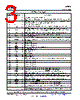
3 / 20 page  www.ti.com bq20z95 SLUS757 – JULY 2007 TERMINAL FUNCTIONS TERMINAL I/O(1) DESCRIPTION NO. NAME 1 DSG O High side N-chan discharge FET gate drive Battery pack input voltage sense input. It also serves as device wake up when device is in shutdown 2 PACK IA, P mode. Positive device supply input. Connect to the center connection of the CHG FET and DSG FET to 3 VCC P ensure device supply either from battery stack or battery pack input 4 ZVCHG O P-chan pre-charge FET gate drive High voltage general purpose open drain output. Can be configured to be used in pre-charge 5 GPOD OD condition Pre-charge mode setting input. Connect to PACK to enable 0v pre-charge using charge FET 6 PMS I connected at CHG pin. Connect to VSS to disable 0V pre-charge using charge FET connected at CHG pin. 7 VSS P Negative device power supply input. Connect all VSS pins together for operation of device 8 REG33 P 3.3V regulator output. Connect at least a 2.2 µF capacitor to REG33 and VSS 9 TOUT P Thermistor bias supply output 10 VCELL+ - Internal cell voltage multiplexer and amplifier output. Connect a 0.1 µF capacitor to VCELL+ and VSS Alert output. In case of short circuit condition, overload condition and watchdog time out this pin will 11 ALERT I/OD be triggered. 12 NC - Not connected 13 TS1 IA Temperature sensor 1 input 14 TS2 IA Temperature sensor 2 input 15 PRES I/OD System / Host present input. Pull up to TOUT 16 PFIN I/OD Fuse blow detection input 17 SAFE I/OD blow fuse signal output 18 SMBD I/OD SMBus data line 19 NC - Not connected 20 SMBC I/OD SMBus clock line 21 DISP I/OD Display enable input 22 VSS P Negative device power supply input. Connect all VSS pins together for operation of device 23 LED1 I LED 1 current sink input 24 LED2 I LED 2 current sink input 25 LED3 I LED 3 current sink input 26 LED4 I LED 4 current sink input 27 LED5 I LED 5 current sink input 28 GSRP IA Coulomb counter differential input. Connect to one side of the sense resistor 29 GSRN IA Coulomb counter differential input. Connect to one side of the sense resistor 30 MRST I Reset input for internal CPU core. connect to RESET for correct operation of device 31 VSS P Negative device power supply input. Connect all VSS pins together for operation of device 32 REG25 P 2.5V regulator output. Connect at least a 1 µF capacitor to REG25 and VSS RAM backup input. Connect a capacitor to this pin and VSS to protect loss of RAM data in case of 33 RBI P short circuit condition 34 VSS P Negative device power supply input. Connect all VSS pins together for operation of device 35 RESET O Reset output. Connect to MSRT. 36 ASRN IA Short circuit and overload detection differential input. Connect to sense resistor 37 ASRP IA Short circuit and overload detection differential input. Connect to sense resistor Cell voltage sense input and cell balancing input for the negative voltage of the bottom cell in cell 38 VC5 IA, P stack. Cell voltage sense input and cell balancing input for the positive voltage of the bottom cell and the 39 VC4 IA, P negative voltage of the second lowest cell in cell stack. (1) I = Input, IA = Analog input, I/O = Input/output, I/OD = Input/Open-drain output, O = Output, OA = Analog output, P = Power Copyright © 2007, Texas Instruments Incorporated Submit Documentation Feedback 3 Product Folder Link(s): bq20z95 |
|
|
链接网址 |
| ALLDATASHEET是否为您带来帮助? [ DONATE ] |
关于 Alldatasheet | 广告服务 | 联系我们 | 隐私政策 | 数据表链接 | 链接交换 | 制造商名单 All Rights Reserved©Alldatasheet.com |
| Russian : Alldatasheetru.com | Korean : Alldatasheet.co.kr | Spanish : Alldatasheet.es | French : Alldatasheet.fr | Italian : Alldatasheetit.com Portuguese : Alldatasheetpt.com | Polish : Alldatasheet.pl | Vietnamese : Alldatasheet.vn Indian : Alldatasheet.in | Mexican : Alldatasheet.com.mx | British : Alldatasheet.co.uk | New Zealand : Alldatasheet.co.nz |
|
Family Site : ic2ic.com |
icmetro.com |
 Chinese ▼
 English
 Chinese
 German
 Japanese
 Russian
 Korean
 Spanish
 French
 Italian
 Portuguese
 Polish
 Vietnamese
 Indian
 Mexican
 British
 New Zealand