|
数据搜索系统,热门电子元器件搜索 |
|
|
数据搜索系统,热门电子元器件搜索 |
|
ADS7890IPFBT.B 数据表(PDF) 7 Page - Texas Instruments |
|
|
|||||||||||||||||||||||||||||
ADS7890IPFBT.B 数据表(HTML) 7 Page - Texas Instruments |
|
|
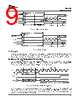
7 / 28 page  ADS7890 SLAS409 − DECEMBER 2003 www.ti.com 7 Terminal Functions PIN NAME I/O DESCRIPTION 31 SDO O Serial data out. Data (excluding MSB) is latched out on the rising of SCLK with MSB first format. MSB is latched with the rising edge of FS or falling edge of CS depending on whether a DSP or SPI interface is used. 36 BUSY O Status output. This pin is high when a conversion is in progress. 39 SCLK I Serial clock. The device needs a minimum of 16 clocks per frame. As described in the timing diagrams, it controls serial data out (first 14 clocks), powerup (from nap) on the 8th rising edge of SCLK, start of sample (track) on the 9th rising edge and end of sample or start of conversion on the 16th falling edge of SCLK. The clock can be stopped after the 16th falling edge. It is important to have minimum jitter on SCLK as it decides the sampling instance and the jitter results in a loss of SNR performance. 41 FS I Frame sync. The rising edge of FS starts a new sample and convert frame. The MSB from the previous conversion is latched out on the rising edge of FS. The rising edge of FS during an internal convert (see Figure 12) aborts the conversion and starts a new frame. 42 CS I Chip Select. Active low signal. The falling edge of CS starts a new sample and convert frame. The MSB from the previous conversion is latched out on the falling edge of CS. This signal can be pulled high after the 16th falling edge of SCLK during the frame. SDO goes to three-state with CS high. The falling edge of CS during internal convert (see Figure 7) aborts the conversion and starts a new frame. 24, 34, 40 +VBD Digital power supply for all digital inputs and outputs. Refer to Table 2 for layout guidelines. 25, 35, 37 BDGND Digital ground for all digital inputs and outputs. Needs to be shorted to analog ground plane below the device. 38 PWD/RST I Active low input, acts as device power down/device reset signal. 5, 8, 11, 12, 14, 15, 44, 45 AGND Analog ground pins. Need to be shorted to analog ground plane below the device. 4, 9, 10, 13, 43, 46 +VA Analog power supplies. Refer to Table 2 for layout guidelines. 6 +IN I Non inverting analog input channel 7 −IN I Inverting analog input channel 1 REFIN I Reference (positive) input. Needs to be decoupled with REFM pin using 0.1- µF bypass capacitor and 1- µF storage capacitor. 2 REFOUT O Internal reference output. To be shorted to REFIN pin when internal reference is used. Do not connect to REFIN pin when external reference is used. Always needs to be decoupled with AGND using 0.1- µF bypass capacitor. 47, 48 REFM I Reference ground. To be connected to analog ground plane. 3, 16 − 23, 26 − 30, 32, 33 NC No connection pins. DESCRIPTION AND TIMING DIAGRAMS DEVICE OPERATION WITH SPI INTERFACE (See Figure 1) Device operation is controlled with CS and SCLK with FS always held high. The frame starts with the falling edge of CS. The MSB is latched out first on the SDO pin. The clock cycle, with the first falling edge after the falling edge of CS, is counted as first clock. Subsequent data bits are latched out on the SDO pin with every rising edge of further clocks (until the 14th rising edge of SCLK). The device has a built-in NAP mode. The device enters the NAP state with an end of conversion and continues to be in this state until the 8th SCLK rising edge. The sampling switch is closed on the 9th SCLK rising edge and the device samples the analog input [+IN− (−IN)] and enters the conversion phase on the 16th SCLK falling edge. The BUSY signal goes high to indicate the conversion is in progress and continues to be high until the end of conversion. A new frame can be started with the end of conversion. |
|
|
链接网址 |
| ALLDATASHEET是否为您带来帮助? [ DONATE ] |
关于 Alldatasheet | 广告服务 | 联系我们 | 隐私政策 | 数据表链接 | 链接交换 | 制造商名单 All Rights Reserved©Alldatasheet.com |
| Russian : Alldatasheetru.com | Korean : Alldatasheet.co.kr | Spanish : Alldatasheet.es | French : Alldatasheet.fr | Italian : Alldatasheetit.com Portuguese : Alldatasheetpt.com | Polish : Alldatasheet.pl | Vietnamese : Alldatasheet.vn Indian : Alldatasheet.in | Mexican : Alldatasheet.com.mx | British : Alldatasheet.co.uk | New Zealand : Alldatasheet.co.nz |
|
Family Site : ic2ic.com |
icmetro.com |
 Chinese ▼
 English
 Chinese
 German
 Japanese
 Russian
 Korean
 Spanish
 French
 Italian
 Portuguese
 Polish
 Vietnamese
 Indian
 Mexican
 British
 New Zealand