|
数据搜索系统,热门电子元器件搜索 |
|
|
数据搜索系统,热门电子元器件搜索 |
|
PCM1728E 数据表(PDF) 10 Page - Texas Instruments |
|
|
|||||||||||||||||||||||||||||
PCM1728E 数据表(HTML) 10 Page - Texas Instruments |
|
|
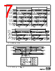
10 / 14 page  ® 10 PCM1728 APPLICATION CONSIDERATIONS DELAY TIME There is a finite delay time in delta-sigma converters. In A/D converters, this is commonly referred to as latency. For a delta-sigma D/A converter, delay time is determined by the order number of the FIR filter stage, and the chosen sampling rate. The following equation expresses the delay time of PCM1728: TD = 30 x 1/fS For fS = 44.1kHz, TD = 30/44.1kHz = 680µs Applications using data from a disc or tape source, such as CD audio, DVD audio, Video CD, DAT, Minidisc, etc., generally are not affected by delay time. For some profes- sional applications such as broadcast audio for studios, it is important for total delay time to be less than 2ms. OUTPUT FILTERING For testing purposes all dynamic tests are done on the PCM1728 using a 20kHz low pass filter. This filter limits the measured bandwidth for THD+N, etc. to 20kHz. Failure to use such a filter will result in higher THD+N and lower SNR and Dynamic Range readings than are found in the specifications. The low pass filter removes out of band noise. Although it is not audible, it may affect dynamic specification numbers. The performance of the internal low pass filter from DC to 40kHz is shown in Figure 10. The higher frequency roll-off of the filter is shown in Figure 11. If the user’s application has the PCM1728 driving a wideband amplifier, it is recom- mended to use an external low pass filter. BYPASSING POWER SUPPLIES The power supplies should be bypassed as close as possible to the unit. Refer to Figure 12 for optimal values of bypass capacitors. 1 10 100 1k 10k 100k 1 0.5 0 –0.5 –1 Log Frequency (Hz) FIGURE 10. Low Pass Filter Response. FIGURE 11. Low Pass Filter Response. POWER SUPPLY CONNECTIONS PCM1728 has four power supply pin for digital (VDD), and analog (VCC). Each connection also has a separate ground. If the power supplies turn on at different times, there is a possibility of a latch-up condition. To avoid this condition, it is recommended to have a common connection between the digital and analog power supplies. If separate supplies are used without a common connection, the delta between the two supplies during ramp-up time must be less than 0.1V. 1 10 100 1k 10k 100k 10M 1M 20 0 –20 –40 –60 –80 –100 Log Frequency (Hz) |
|
|
链接网址 |
| ALLDATASHEET是否为您带来帮助? [ DONATE ] |
关于 Alldatasheet | 广告服务 | 联系我们 | 隐私政策 | 数据表链接 | 链接交换 | 制造商名单 All Rights Reserved©Alldatasheet.com |
| Russian : Alldatasheetru.com | Korean : Alldatasheet.co.kr | Spanish : Alldatasheet.es | French : Alldatasheet.fr | Italian : Alldatasheetit.com Portuguese : Alldatasheetpt.com | Polish : Alldatasheet.pl | Vietnamese : Alldatasheet.vn Indian : Alldatasheet.in | Mexican : Alldatasheet.com.mx | British : Alldatasheet.co.uk | New Zealand : Alldatasheet.co.nz |
|
Family Site : ic2ic.com |
icmetro.com |
 Chinese ▼
 English
 Chinese
 German
 Japanese
 Russian
 Korean
 Spanish
 French
 Italian
 Portuguese
 Polish
 Vietnamese
 Indian
 Mexican
 British
 New Zealand