24 / 58 page
IP113M LF
Preliminary Data Sheet
2.6
Link fault pass through
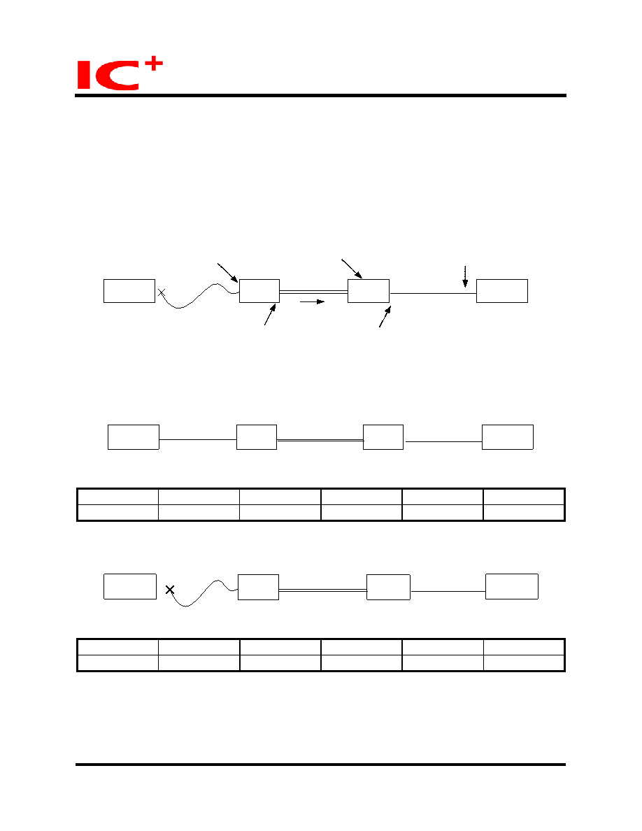
When link fault pass through function is enabled, link status on TX port will inform the FX port of the same
device and vice versa. From the link fault pass through procedure illustrates in the figure below, if link fail
happens on IP113M LF’s TX port (1), the local FX port sends non-idle pattern to notice the remote FX port
(2). The remote FX port then forces its TX port to link failed after receiving the non-idle pattern (4). In other
words, this mechanism will alert the link fault status of local TX port to the remote converter’s TX port, and
the link status of the remote TX port will become off. Link status LED will also be off for both IP113M LF
and its link partner.
IP113M
LF
IP113M
LF
UTP
Fiber
Switch1 or
NIC 1
Switch2 or
NIC 2
(1) TP port link failed
link off
The procedure of link fault pass through
(3) fiber port gets remote
link fault information
(4) TP link fail
(5) remote TP
link is off
(2) fiber port sends
non-idle pattern
UTP
local
remote
2.6.1
Normal case
IP113M
LF
IP113M
LF
UTP
UT
Fiber
P
Switch1
Switch2
LED
SW1
LED_TP_LINK1 LED_FX_LINK1
LED
SW2
local
remote
LED_FX_LINK2 LED_TP_LINK2
Link LED on SW1
LED_TP_LINK1 LED_FX_LINK1 LED_FX_LINK2 LED_TP_LINK2 Link LED on SW2
ON
ON
ON
ON
ON
ON
2.6.2
Remote TP port disconnected
IP113M
LF
IP113M
LF
Fiber
Switch1
Switch2
LED
SW1
LED
SW2
local
remote
LED_TP_LINK1 LED_FX_LINK1
LED_FX_LINK2 LED_TP_LINK2
UTP
UTP
disconnected
Link LED on SW1
LED_TP_LINK1 LED_FX_LINK1 LED_FX_LINK2 LED_TP_LINK2 Link LED on SW2
Off
Off
Off
Off
Off
Off
24/58
April 9, 2007
Copyright © 2004, IC Plus Corp.
IP113M LF-DS-R11

 Chinese ▼
 English
 Chinese
 German
 Japanese
 Russian
 Korean
 Spanish
 French
 Italian
 Portuguese
 Polish
 Vietnamese
 Indian
 Mexican
 British
 New Zealand