2 / 22 page
IP113A LF
Preliminary Data Sheet
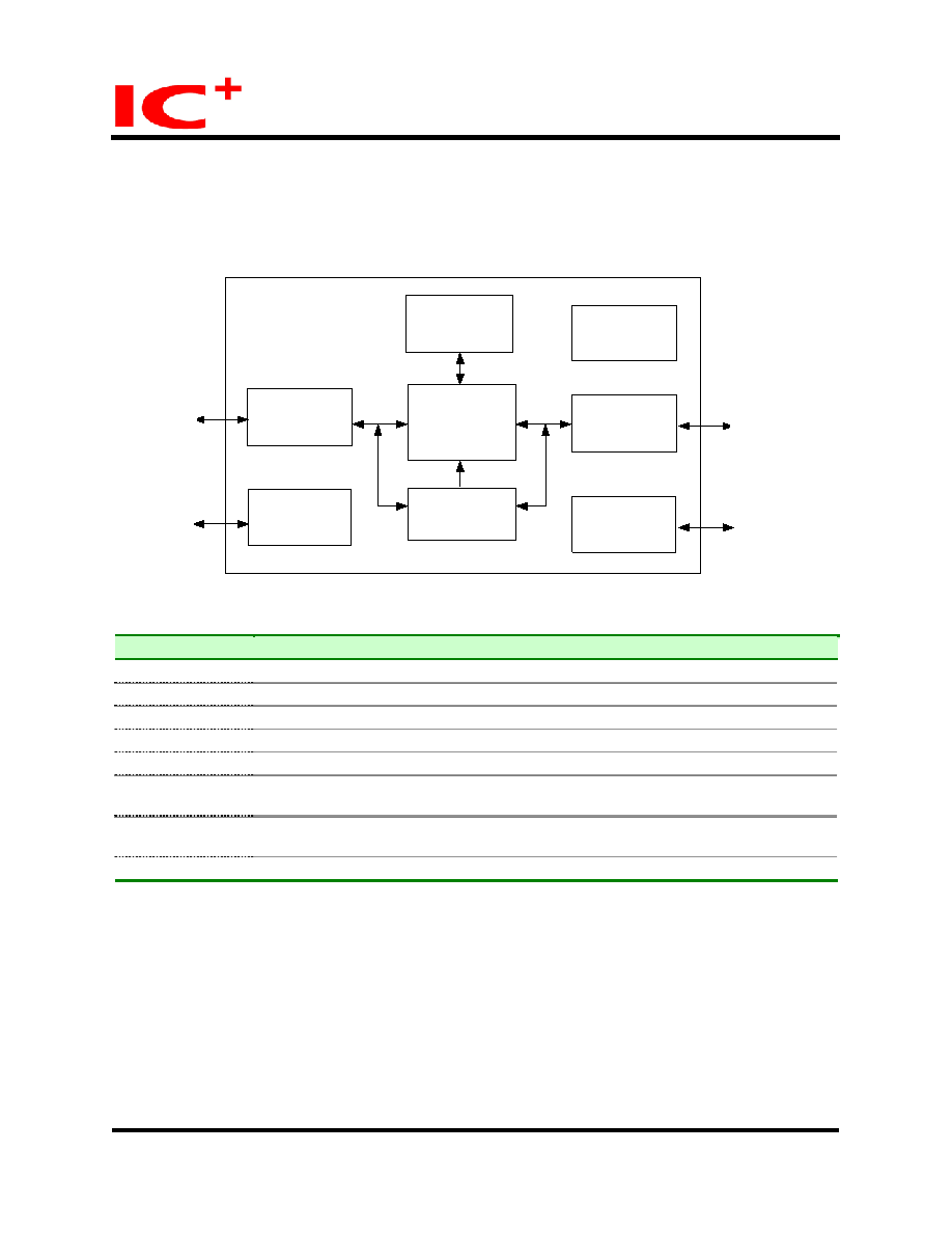
Block Diagram
10/100M TX
PHY
Two port switch
SSRAM
EEPROM
I/F
100M FX
PLL/ Clock
Generator
LED
I/F
Forward Mode
Control
RXIP
RXIM
SCL
SDA
MII
MII
LED
TXOP
TXOM
FXSD
FXRDP
FXRDM
FXTDP
FXTDM
Revision History
Revision #
Change Description
IP113A LF-DS-R01 Initial release.
IP113A LF-DS-R02 Remove Operation Junction Temperature.
IP113A LF-DS-R03 TP port should be linked at 100M full duplex when working at this mode.
IP113A LF-DS-R04 Add the order information for lead free package.
IP113A LF-DS-R05 Revise the diagram.
IP113A LF-DS-R06 TP_FORCE (Pin24) &X_EN(Pin29)
It is an input pin during reset period. The default value is latched at the end of reset.
IP113A LF-DS-R07 Remove internal pull-high resistance & pull-low resistance on page 5.
Modify the IPL : pull-low and IPH : pull-high
IP113A LF-DS-R08 Add Power Pin description on Page10
April 9, 2007
2/22
Copyright © 2004, IC Plus Corp.
IP113A LF-DS-R08

 Chinese ▼
 English
 Chinese
 German
 Japanese
 Russian
 Korean
 Spanish
 French
 Italian
 Portuguese
 Polish
 Vietnamese
 Indian
 Mexican
 British
 New Zealand