IP113M LF
Preliminary Data Sheet
12/58
April 9, 2007
Copyright © 2004, IC Plus Corp.
IP113M LF-DS-R11
PIN Description (continued)
Pin no.
Label
Type
Description
MC operation mode
21
LFP
IPL
Link fault pass through (LFP)
1: enable
Link status of one port is forwarded to the other port.
0: disable (default)
22
23
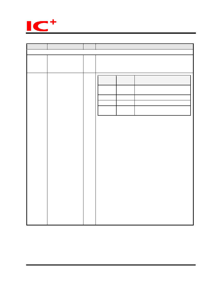
DIRECT_WIRE
FAST_FWD
IPL
DIRECT_
WIRE
FAST_F
WD
Function
0
0
Store and forward switch mode
(default)
0
1
Modified cut-through switch mode
1
0
Converter mode
1
1
Converter mode with
auto-change-forward function
Store and forward switch mode:
IP113M LF begins to forward a frame at the end of
receiving a frame completely.
Modified cut-through switch mode:
IP113M LF begins to forward a frame after the first 64
bytes data received. TP port should be forced at 100M at
this mode.
Converter mode:
Incoming frames are not buffered in IP113M LF to achieve
the min latency. Both TP port and fiber port of IP113M LF
should work at 100M full duplex in this mode. If TP port is
linked at half duplex, the total length of UTP cable and
fiber should be less than 60 meters to meet the
requirement of CSMACD in IEEE802.3.
Converter mode with auto-change-forward function:
IP113M LF will change forward mode itself if it detects the
speed is different in TP port and FX port.
In converter mode, IP113M LF forwards IEEE802.3x
pause frame directly. In the other modes, IP113M LF
doesn’t forward IEEE802.3x pause frame directly, it sends
out pause frame when its internal buffer is full.

 Chinese ▼
 English
 Chinese
 German
 Japanese
 Russian
 Korean
 Spanish
 French
 Italian
 Portuguese
 Polish
 Vietnamese
 Indian
 Mexican
 British
 New Zealand