15 / 60 page 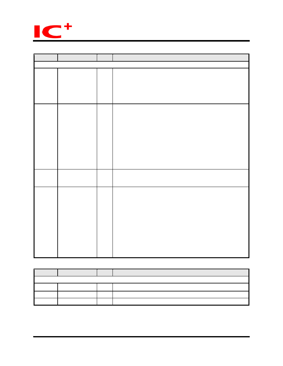 IP175A LF Preliminary Data Sheet 15/60 February 20, 2006 Copyright © 2004, IC Plus Corp. IP175A LF-DS-R08 Pin Descriptions (continued) Pin no. Label Type Description Transceiver 127, 128, 11, 12, 18,19, 29, 30, 33, 34 RXIP0, RXIM0, RXIP1, RXIM1, RXIP2, RXIM2, RXIP3, RXIM3, RXIP4, RXIM4 I TP receive 3, 4, 8, 9, 21, 22, 26, 27, 37, 38 TXOP0, TXOM0, TXOP1, TXOM1, TXOP2, TXOM2, TXOP3, TXOM3, TXOP4, TXOM4 O TP transmit 14 BGRES O Band gap resister. It is connected to GND through a 6.2 k ohms resistor. Please refer to application circuit for more information. 125, 41, 42, 43, 44 FXSD0~4 I 100Base-FX Signal detect IP175A LF will latch the value on FXSDx pins at the end of reset to decide if the port works at 100BaseFX mode. A port works in 100BaseFX mode, if its corresponding signal FXSDx > 0.6v at the end of reset. FXSDx should be connected to GND if the port works in TP mode. That is, a port is a fiber port if its FXSDx is connected to the SD of fiber MAU and a port is a TP port if its FXSDx is connected to GND. The SD of fiber port is active if the voltage of FXSDx is higher than 1.2v. It is used to inform IP175A LF if the fiber is plugged or not. Pin no. Label Type Description Misc. 123 X1 I 25M system clock input 122 X2 O Crystal pin 93 RESETB I Reset, low active |
|

 Chinese ▼
 English
 Chinese
 German
 Japanese
 Russian
 Korean
 Spanish
 French
 Italian
 Portuguese
 Polish
 Vietnamese
 Indian
 Mexican
 British
 New Zealand