|
数据搜索系统,热门电子元器件搜索 |
|
|
数据搜索系统,热门电子元器件搜索 |
|
AD8065ARTZ-R2 数据表(PDF) 19 Page - Analog Devices |
|
|
|||||||||||||||||||||||||||||
AD8065ARTZ-R2 数据表(HTML) 19 Page - Analog Devices |
|
|
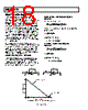
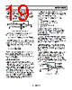
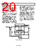
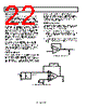
19 / 28 page  AD8065/AD8066 Rev. G | Page 19 of 28 The closed-loop bandwidth is inversely proportional to the noise gain of the op amp circuit, (RF + RG )/RG. This simple model is accurate for noise gains above 2. The actual bandwidth of circuits with noise gains at or below 2 are higher than those predicted with this model due to the influence of other poles in the frequency response of the real op amp. VO RF A RG VI Ib– RS Ib+ +VOS – Figure 54. Voltage Feedback Amplifier DC Errors Figure 54 shows a voltage feedback amplifier’s dc errors. For both inverting and noninverting configurations () ⎟ ⎠ ⎞ ⎜ ⎝ ⎛ + + × − ⎟ ⎠ ⎞ ⎜ ⎝ ⎛ + × = − + G F G OS F b G F G S b O R R R V R I R R R R I error V The voltage error due to Ib+ and Ib– is minimized if RS = RF || RG (though with the AD8065 input currents at less than 20 pA over temperature, this is likely not a concern). To include common- mode and power supply rejection effects, total VOS can be modeled CMR V PSR V V V CM S nom OS OS Δ Δ + + = nom OS V is the offset voltage specified at nominal conditions, ΔVS is the change in power supply from nominal conditions, PSR is the power supply rejection, ΔVCM is the change in common-mode voltage from nominal conditions, and CMR is the common-mode rejection. WIDEBAND OPERATION Figure 42 through Figure 44 show the circuits used for wideband characterization for gains of +1, +2, and −1. Source impedance at the summing junction (RF || RG) will form a pole in the amplifier’s loop response with the amplifier’s input capacitance of 6.6 pF. This can cause peaking and ringing if the time constant formed is too low. Feedback resistances of 300 Ω to 1 kΩ are recommended, since they will not unduly load down the amplifier and the time constant formed will not be too low. Peaking in the frequency response can be compensated for with a small capacitor (CF) in parallel with the feedback resistor, as illustrated in Figure 12. This shows the effect of different feedback capacitances on the peaking and bandwidth for a noninverting G = +2 amplifier. For the best settling times and the best distortion, the impedances at the AD8065/AD8066 input terminals should be matched. This minimizes nonlinear common-mode capacitive effects that can degrade ac performance. Actual distortion performance depends on a number of variables: • The closed-loop gain of the application • Whether it is inverting or noninverting • Amplifier loading • Signal frequency and amplitude • Board layout Also see Figure 16 to Figure 20. The lowest distortion is obtained with the AD8065 used in low gain inverting appli- cations, since this eliminates common-mode effects. Higher closed-loop gains result in worse distortion performance. INPUT PROTECTION The inputs of the AD8065/AD8066 are protected with back-to- back diodes between the input terminals as well as ESD diodes to either power supply. This results in an input stage with picoamps of input current that can withstand up to 1500 V ESD events (human body model) with no degradation. Excessive power dissipation through the protection devices destroys or degrades the performance of the amplifier. Differ- ential voltages greater than 0.7 V result in an input current of approximately (|V+ − V−| 0.7 V)/RI, where RI is the resistance in series with the inputs. For input voltages beyond the positive supply, the input current is approximately (VI − VCC − 0.7)/RI. Beyond the negative supply, the input current is about (VI − VEE + 0.7)/RI. If the inputs of the amplifier are to be subjected to sustained differential voltages greater than 0.7 V, or to input voltages beyond the amplifier power supply, input current should be limited to 30 mA by an appropriately sized input resistor (RI), as shown in Figure 55. RI VI VO AD8065 RI > (| V+–V– | – 0.7V) 30mA FOR LARGE | V+ –V– | RI > (VI –VEE – 0.7V) 30mA RI > (VI –VEE + 0.7V) 30mA FOR VI BEYOND SUPPLY VOLTAGES Figure 55. Current-Limiting Resistor |
|
|
链接网址 |
| ALLDATASHEET是否为您带来帮助? [ DONATE ] |
关于 Alldatasheet | 广告服务 | 联系我们 | 隐私政策 | 数据表链接 | 链接交换 | 制造商名单 All Rights Reserved©Alldatasheet.com |
| Russian : Alldatasheetru.com | Korean : Alldatasheet.co.kr | Spanish : Alldatasheet.es | French : Alldatasheet.fr | Italian : Alldatasheetit.com Portuguese : Alldatasheetpt.com | Polish : Alldatasheet.pl | Vietnamese : Alldatasheet.vn Indian : Alldatasheet.in | Mexican : Alldatasheet.com.mx | British : Alldatasheet.co.uk | New Zealand : Alldatasheet.co.nz |
|
Family Site : ic2ic.com |
icmetro.com |
 Chinese ▼
 English
 Chinese
 German
 Japanese
 Russian
 Korean
 Spanish
 French
 Italian
 Portuguese
 Polish
 Vietnamese
 Indian
 Mexican
 British
 New Zealand