|
数据搜索系统,热门电子元器件搜索 |
|
|
数据搜索系统,热门电子元器件搜索 |
|
AD8606ARMZ-R2 数据表(PDF) 19 Page - Analog Devices |
|
|
|||||||||||||||||||||||||||||
AD8606ARMZ-R2 数据表(HTML) 19 Page - Analog Devices |
|
|
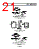
19 / 24 page  AD8605/AD8606/AD8608 Rev. H | Page 19 of 24 INSTRUMENTATION AMPLIFIERS The low offset voltage and low noise of the AD8605 make it an ideal amplifier for instrumentation applications. Difference amplifiers are widely used in high accuracy circuits to improve the common-mode rejection ratio. Figure 53 shows a simple difference amplifier. Figure 54 shows the common- mode rejection for a unity gain configuration and for a gain of 10. Making (R4/R3) = (R2/R1) and choosing 0.01% tolerance yields a CMRR of 74 dB and minimizes the gain error at the output. AD8605 5V V2 V1 R1 1kΩ R3 1kΩ R2 10kΩ R4 10kΩ VOUT R4 R3 R2 R1 = VOUT = (V2 – V1) R2 R1 Figure 53. Difference Amplifier, AV = 10 FREQUENCY (Hz) 120 100 0 100 10M 1k 10k 100k 1M 60 40 20 80 AV = 10 VSY = ±2.5V AV = 1 Figure 54. Difference Amplifier CMRR vs. Frequency DAC CONVERSION The low input bias current and offset voltage of the AD8605 make it an excellent choice for buffering the output of a current output DAC. Figure 55 shows a typical implementation of the AD8605 at the output of a 12-bit DAC. The DAC8143 output current is converted to a voltage by the feedback resistor. The equivalent resistance at the output of the DAC varies with the input code, as does the output capacitance. R2 AD8605 VOS RF CF R2 R2 V+ V– RR R VREF Figure 55. Simplified Circuit of the DAC8143 with AD8605 Output Buffer To optimize the performance of the DAC, insert a capacitor in the feedback loop of the AD8605 to compensate the amplifier for the pole introduced by the output capacitance of the DAC. Typical values for CF range from 10 pF to 30 pF; it can be adjusted for the best frequency response. The total error at the output of the op amp can be computed by ⎟⎟ ⎠ ⎞ ⎜⎜ ⎝ ⎛ + = 1 Req R V E F OS O where Req is the equivalent resistance seen at the output of the DAC. As previously mentioned, Req is code dependent and varies with the input. A typical value for Req is 15 kΩ. Choosing a feedback resistor of 10 kΩ yields an error of less than 200 μV. Figure 56 shows the implementation of a dual-stage buffer at the output of a DAC. The first stage is used as a buffer. Capacitor C1 with Req creates a low-pass filter, and thus, provides phase lead to compensate for frequency response. The second stage of the AD8606 is used to provide voltage gain at the output of the buffer. Grounding the positive input terminals in both stages reduces errors due to the common-mode output voltage. Choosing R1, R2, and R3 to match within 0.01% yields a CMRR of 74 dB and maintains minimum gain error in the circuit. RFB VDD DB11 OUT1 AD7545 AGND RCS RP VIN 15V VOUT VREF 1/2 AD8606 1/2 AD8606 C1 33pF R4 5kΩ R2 10kΩ R1 10kΩ R3 20kΩ Figure 56. Bipolar Operation |
|
|
链接网址 |
| ALLDATASHEET是否为您带来帮助? [ DONATE ] |
关于 Alldatasheet | 广告服务 | 联系我们 | 隐私政策 | 数据表链接 | 链接交换 | 制造商名单 All Rights Reserved©Alldatasheet.com |
| Russian : Alldatasheetru.com | Korean : Alldatasheet.co.kr | Spanish : Alldatasheet.es | French : Alldatasheet.fr | Italian : Alldatasheetit.com Portuguese : Alldatasheetpt.com | Polish : Alldatasheet.pl | Vietnamese : Alldatasheet.vn Indian : Alldatasheet.in | Mexican : Alldatasheet.com.mx | British : Alldatasheet.co.uk | New Zealand : Alldatasheet.co.nz |
|
Family Site : ic2ic.com |
icmetro.com |
 Chinese ▼
 English
 Chinese
 German
 Japanese
 Russian
 Korean
 Spanish
 French
 Italian
 Portuguese
 Polish
 Vietnamese
 Indian
 Mexican
 British
 New Zealand