|
数据搜索系统,热门电子元器件搜索 |
|
|
数据搜索系统,热门电子元器件搜索 |
|
M24512-RMW6 数据表(PDF) 4 Page - STMicroelectronics |
|
|
|||||||||||||||||||||||||||||
M24512-RMW6 数据表(HTML) 4 Page - STMicroelectronics |
|
|
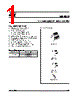
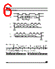
4 / 24 page  M24512 4/24 SUMMARY DESCRIPTION These I2C-compatible electrically erasable pro- grammable memory (EEPROM) devices are orga- nized as 64K x 8 bits. Figure 2. Logic Diagram Table 2. Signal Names I2C uses a two-wire serial interface, comprising a bi-directional data line and a clock line. The devic- es carry a built-in 4-bit Device Type Identifier code (1010) in accordance with the I2C bus definition. The device behaves as a slave in the I2C protocol, with all memory operations synchronized by the serial clock. Read and Write operations are initiat- ed by a Start condition, generated by the bus mas- ter. The Start condition is followed by a Device Select Code and Read/Write bit (RW) (as de- scribed in Table 3.), terminated by an acknowl- edge bit. When writing data to the memory, the device in- serts an acknowledge bit during the 9th bit time, following the bus master’s 8-bit transmission. When data is read by the bus master, the bus master acknowledges the receipt of the data byte in the same way. Data transfers are terminated by a Stop condition after an Ack for Write, and after a NoAck for Read. Power On Reset In order to prevent data corruption and inadvertent Write operations during Power-up, a Power On Reset (POR) circuit is included. At Power-up, the device will not respond to any command until VCC has reached the Power On Reset threshold volt- age (this threshold is lower than the VCC min oper- ating voltage defined in Tables 8 and 9). In the same way, as soon as VCC drops from the normal operating voltage, below the Power On Reset threshold voltage, the device stops to respond to any command. Prior to selecting and issuing commands to the memory, a valid and stable VCC voltage must be applied. This voltage must remain stable and valid until the end of the transmission of the command and, for a Write instruction, until the completion of the internal write cycle (tW). Figure 3. DIP, SO and TSSOP Connections Note: See PACKAGE MECHANICAL section for package dimen- sions, and how to identify pin-1. E0, E1, E2 Chip Enable SDA Serial Data SCL Serial Clock WC Write Control VCC Supply Voltage VSS Ground AI02275 SDA VCC M24512 WC SCL VSS 3 E0-E2 1 AI04035B 2 3 4 8 7 6 5 SDA VSS SCL WC E1 E0 VCC E2 M24512 |
|
|
链接网址 |
| ALLDATASHEET是否为您带来帮助? [ DONATE ] |
关于 Alldatasheet | 广告服务 | 联系我们 | 隐私政策 | 数据表链接 | 链接交换 | 制造商名单 All Rights Reserved©Alldatasheet.com |
| Russian : Alldatasheetru.com | Korean : Alldatasheet.co.kr | Spanish : Alldatasheet.es | French : Alldatasheet.fr | Italian : Alldatasheetit.com Portuguese : Alldatasheetpt.com | Polish : Alldatasheet.pl | Vietnamese : Alldatasheet.vn Indian : Alldatasheet.in | Mexican : Alldatasheet.com.mx | British : Alldatasheet.co.uk | New Zealand : Alldatasheet.co.nz |
|
Family Site : ic2ic.com |
icmetro.com |
 Chinese ▼
 English
 Chinese
 German
 Japanese
 Russian
 Korean
 Spanish
 French
 Italian
 Portuguese
 Polish
 Vietnamese
 Indian
 Mexican
 British
 New Zealand