|
数据搜索系统,热门电子元器件搜索 |
|
|
数据搜索系统,热门电子元器件搜索 |
|
ADL5604ACPZ-R7 数据表(PDF) 21 Page - Analog Devices |
|
|
|||||||||||||||||||||||||||||
ADL5604ACPZ-R7 数据表(HTML) 21 Page - Analog Devices |
|
|
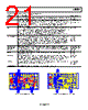
21 / 24 page  ADL5604 Rev. 0 | Page 21 of 24 Table 7. Evaluation Board Configuration Options, 2140 MHz Component Function/Notes Default Value C1, C2 Input/output dc blocking capacitors at 2140 MHz. C3 provides dc blocking; therefore, a jumper is installed in place of C1. C1 = 0 Ω, C2 = 22 pF C3, C4 Input matching capacitors. The input match is set for 2140 MHz but is easily changed for other frequencies. C3 is set at a specific distance from C4 so that the microstrip line can act as inductance for part of the match. If space is at a premium, an inductor can take the place of the microstrip line. The ADL5604 is sensitive to the input match; therefore, the tolerance of these components and their placement must be tight. C3 = 1.3 pF HQ, C4 = 2.7 pF HQ C5 Output matching capacitor. The output match is set for 2140 MHz but is easily changed for other frequencies. The tolerance for this capacitor should be tight. C5 is set at a specific distance from the input; therefore, the microstrip line can act as inductance for part of the match. If space is at a premium, an inductor can take the place of the microstrip line. There is a short length of low impedance line on the output that is embedded in the match. The ADL5604 is less sensitive to the output match than the input match, but the tolerance still must be tight. C5 = 2.4 pF L1, L2, R9, R10 The main bias for the ADL5604 comes through L1 to its output. L1 should be high impedance for the frequency of operation, while providing low resistance for the dc current. The evaluation board uses a Coilcraft 0603HP-16NX_H inductor. It is a 16 nH inductor, which provides some of the match at 2140 MHz. As the operating frequency gets lower, the inductance must increase, but as the inductance increases, the current is more limited for a 0603 package. R9 and R10 can be removed and L2 added to allow for low frequency operation. L2 has the footprint for a Coilcraft SLC7530D-101MLB (0.4 μH). L1 = 16 nH, L2 = open, R9 = 0 Ω, R10 = 0 Ω C6, C7, C8, C9, C10, C11, C12, C14, C15 Power supply decoupling. The need for power supply decoupling capacitance is based on the noise and potential for noise on the power supply. The smallest capacitor should be the closest to the ADL5604. The main bias that goes through RFOUT is the most sensitive to noise because the bias is connected directly to the output. C6, C9, C11 = 10nF, C7, C10, C12, C14, C15 = 0.1uF, C8 = 10 uF R6, R8 R6 and R8 can be removed to eliminate any parasitic elements of VBIAS and VCC2 if a fast response time is required. R6 = 0 Ω, R8 = 0 Ω R2, R4, R5 The ADL5604 can be shut down using VBIAS alone or VBIAS and VCC2. The ADL5604 has a shutdown current of 13 mA when only VBIAS is used. The shutdown current is < 1 μA if VBIAS and VCC2 are used. However, VCC2 draws 5 mA when biased, setting the current drive capability of the shutdown controller. R2, R4, and R5 allow custom configuration of the shutdown. R2, R5 = 0 Ω, R4 = open U2, R1, R3 If VCC2 is used to shut down the ADL5604, 5 mA must be sourced when the part is enabled. U2, R1, and R3 are configured as a buffer to source the 5 mA. U2 = AD8009, R1 = 3.01 Ω, R3 = open Exposed Paddle The paddle should be connected to both thermal and electrical ground. Figure 44. Evaluation Board Layout, Topside Figure 45. Evaluation Board Layout, Bottom Side |
|
|
链接网址 |
| ALLDATASHEET是否为您带来帮助? [ DONATE ] |
关于 Alldatasheet | 广告服务 | 联系我们 | 隐私政策 | 数据表链接 | 链接交换 | 制造商名单 All Rights Reserved©Alldatasheet.com |
| Russian : Alldatasheetru.com | Korean : Alldatasheet.co.kr | Spanish : Alldatasheet.es | French : Alldatasheet.fr | Italian : Alldatasheetit.com Portuguese : Alldatasheetpt.com | Polish : Alldatasheet.pl | Vietnamese : Alldatasheet.vn Indian : Alldatasheet.in | Mexican : Alldatasheet.com.mx | British : Alldatasheet.co.uk | New Zealand : Alldatasheet.co.nz |
|
Family Site : ic2ic.com |
icmetro.com |
 Chinese ▼
 English
 Chinese
 German
 Japanese
 Russian
 Korean
 Spanish
 French
 Italian
 Portuguese
 Polish
 Vietnamese
 Indian
 Mexican
 British
 New Zealand