|
数据搜索系统,热门电子元器件搜索 |
|
|
数据搜索系统,热门电子元器件搜索 |
|
RH5RH552B-T2 数据表(PDF) 13 Page - RICOH electronics devices division |
|
|
|||||||||||||||||||||||||||||
RH5RH552B-T2 数据表(HTML) 13 Page - RICOH electronics devices division |
|
|
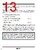
13 / 29 page  The above explanation is directed to the calculation in an ideal case where there is no energy loss caused by the resistance in the external components and LxSW. In an actual case, the maximum output current will be 50 to 80% of the above calculated maximum output current. In particular, care must be taken because VIN is decreased in an amount corresponding to the voltage drop caused by LxSW when IL is large or VIN is low. Furthermore, it is required that with respect to VOUT, Vf of the diode (about 0.3V in the case of a Schottky type diode) be taken into consideration. 12 RH5RH Therefore it is necessary that the setting of the input/output conditions and the selection of peripheral compo- nents should be made with ILmax taken into consideration. • Output Current in Continuous Conduction Mode When the operation enters into the continuous conduction mode by increasing the IOUT, ILmin becomes equal to Iconst (> 0), and this current always flows through the inductor. Therefore, VIN · Iconst is added to PIN in Equation 5. Thus, PIN=VIN · Iconst+(PON+POFF)/T=VOUT ·IOUT=POUT When the above Equation is solved for IOUT, IOUT=VIN 2 · tonc2/(2 · L · T · (VOUT–VIN))+VIN · Iconst/VOUT ............................................Equation 8 The peak current which flows through L · LxTr · SD is ILmax=VIN · ton/L+Iconst ...................................................................................................Equation 9 From Equations 6 and 9, the larger the value of L, the smaller the load current at which the operation enters into the continuous mode, and the smaller the difference between ILmax and ILmin, and the smaller the value of ILmax. Therefore, when the load current is the same, the larger the value of L, the easier the selection of peripheral components with a small allowable current becomes, and the smaller the ripple of the peripheral components can be made. In this case, however, it must be noted from Equation 6 that IOUT becomes small when the allowable cur- rent of the inductor is small or when VIN is so small that the operation cannot enter into the continuous mode. HINTS |
|
|
链接网址 |
| ALLDATASHEET是否为您带来帮助? [ DONATE ] |
关于 Alldatasheet | 广告服务 | 联系我们 | 隐私政策 | 数据表链接 | 链接交换 | 制造商名单 All Rights Reserved©Alldatasheet.com |
| Russian : Alldatasheetru.com | Korean : Alldatasheet.co.kr | Spanish : Alldatasheet.es | French : Alldatasheet.fr | Italian : Alldatasheetit.com Portuguese : Alldatasheetpt.com | Polish : Alldatasheet.pl | Vietnamese : Alldatasheet.vn Indian : Alldatasheet.in | Mexican : Alldatasheet.com.mx | British : Alldatasheet.co.uk | New Zealand : Alldatasheet.co.nz |
|
Family Site : ic2ic.com |
icmetro.com |
 Chinese ▼
 English
 Chinese
 German
 Japanese
 Russian
 Korean
 Spanish
 French
 Italian
 Portuguese
 Polish
 Vietnamese
 Indian
 Mexican
 British
 New Zealand