|
数据搜索系统,热门电子元器件搜索 |
|
|
数据搜索系统,热门电子元器件搜索 |
|
ADA4891-2ARMZ-R7 数据表(PDF) 15 Page - Analog Devices |
|
|
|||||||||||||||||||||||||||||
ADA4891-2ARMZ-R7 数据表(HTML) 15 Page - Analog Devices |
|
|
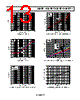
15 / 24 page  ADA4891-1/ADA4891-2/ADA4891-3/ADA4891-4 Rev. B | Page 15 of 24 APPLICATIONS INFORMATION USING THE ADA4891 Understanding the subtleties of the ADA4891 family of amplifiers provides insight into how to extract the peak performance from the device. The following sections describe the effect of gain, component values, and parasitics on the performance of the ADA4891. The wideband, noninverting gain configuration of the ADA4891 is shown in Figure 50; the wideband, inverting gain configuration of the ADA4891 is shown in Figure 51. WIDEBAND, NONINVERTING GAIN OPERATION ADA4891 RF RG RT 50Ω SOURCE RL +VS –VS 10µF 0.1µF VI VO 10µF 0.1µF Figure 50. Noninverting Gain Configuration In Figure 50, RF and RG denote the feedback and gain resistors, respectively. Together, RF and RG determine the noise gain of the amplifier. The value of RF defines the 0.1 dB bandwidth (for more information, see the Effect of RF on 0.1 dB Gain Flatness section). Typical RF values range from 549 Ω to 698 Ω for the ADA4891-1/ADA4891-2. Typical RF values range from 301 Ω to 453 Ω for the ADA4891-3/ADA4891-4. In a controlled impedance signal path, RT is used as the input termination resistor designed to match the input source imped- ance. Note that RT is not required for normal operation. RT is generally set to match the input source impedance. WIDEBAND, INVERTING GAIN OPERATION ADA4891 RF RT RG 50Ω SOURCE RL +VS –VS VI VO 10µF 0.1µF 10µF 0.1µF Figure 51. Inverting Gain Configuration Figure 51 shows the inverting gain configuration. For the inverting gain configuration, set the parallel combination of RT and RG to match the input source impedance. Note that a bias current cancellation resistor is not required in the noninverting input of the amplifier because the input bias current of the ADA4891 is very low (less than 2 pA). Therefore, the dc errors caused by the bias current are negligible. For both noninverting and inverting gain configurations, it is often useful to increase the RF value to decrease the load on the output. Increasing the RF value improves harmonic distortion at the expense of reducing the 0.1 dB bandwidth of the amplifier. This effect is discussed further in the Effect of RF on 0.1 dB Gain Flatness section. RECOMMENDED VALUES Table 5 and Table 6 provide a quick reference for various configu- rations and show the effect of gain on the −3 dB small-signal bandwidth, slew rate, and peaking of the ADA4891-1/ADA4891-2/ ADA4891-3/ADA4891-4. Note that as the gain increases, the small-signal bandwidth decreases, as is expected from the gain bandwidth product relationship. In addition, the phase margin improves with higher gains, and the amplifier becomes more stable. As a result, the peaking in the frequency response is reduced (see Figure 7 and Figure 10). Table 5. Recommended Component Values and Effect of Gain on ADA4891-1/ADA4891-2 Performance (RL = 1 kΩ) Feedback Network Values −3 dB Small-Signal Bandwidth (MHz) Slew Rate (V/μs) Peaking (dB) Gain RF (Ω) RG (Ω) VOUT = 200 mV p-p tR tF −1 604 604 118 188 192 1.3 +1 0 Open 240 154 263 2.6 +2 604 604 120 170 210 1.4 +5 604 151 32.5 149 154 0 +10 604 67.1 12.7 71 72 0 |
|
|
链接网址 |
| ALLDATASHEET是否为您带来帮助? [ DONATE ] |
关于 Alldatasheet | 广告服务 | 联系我们 | 隐私政策 | 数据表链接 | 链接交换 | 制造商名单 All Rights Reserved©Alldatasheet.com |
| Russian : Alldatasheetru.com | Korean : Alldatasheet.co.kr | Spanish : Alldatasheet.es | French : Alldatasheet.fr | Italian : Alldatasheetit.com Portuguese : Alldatasheetpt.com | Polish : Alldatasheet.pl | Vietnamese : Alldatasheet.vn Indian : Alldatasheet.in | Mexican : Alldatasheet.com.mx | British : Alldatasheet.co.uk | New Zealand : Alldatasheet.co.nz |
|
Family Site : ic2ic.com |
icmetro.com |
 Chinese ▼
 English
 Chinese
 German
 Japanese
 Russian
 Korean
 Spanish
 French
 Italian
 Portuguese
 Polish
 Vietnamese
 Indian
 Mexican
 British
 New Zealand