|
数据搜索系统,热门电子元器件搜索 |
|
|
数据搜索系统,热门电子元器件搜索 |
|
300-R010-45L 数据表(PDF) 6 Page - Magnetrol International, Inc. |
|
|
|||||||||||||||||||||||||||||
300-R010-45L 数据表(HTML) 6 Page - Magnetrol International, Inc. |
|
|
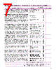
6 / 12 page  MEASUREMENT RANGE EXPECTATIONS Ultrasonic non-contact devices are typically rated for a maximum range in ideal conditions. Experience has shown that maximum range must be adjusted for cer- tain factors. Although the maximum range rating is somewhat conservative, each application must be evaluated for specific conditions. The operating parameters listed below can impact the maximum range of measurement: • Surface agitation • Vapors and steam (as measured by temperature difference between liquid and air) • Beam spread interference • Sensor alignment • Foam • Dust • Air movement • Ambient temperature • Pressure HOW TO CALCULATE To estimate how successful a particular application may be, using the chart on page 3: 1. Select one condition from each of the operating parameters that best describes your application. 2. Enter the corresponding performance multiplier value in the application column. 3. Multiply all values together. 4. Obtain the maximum range from the table below that corresponds to your switch or transmitter model. 5. Multiply step 3 by step 4; this yields a value that is the maximum allowable measurement range for this application. Example: The vessel is a closed-top tank, uninsulated, 22 feet tall. Surface agitation: Expect slight agitation from fill line. Performance multiplier 0.9 Vapor and steam: The process temperature is +130° F; slight vapor is expected. Performance multiplier 0.9 Beam interference: No interference exists. Performance multiplier 1.0 Sensor alignment: The sensor will be perpendicular to the liquid surface. Performance multiplier 1.0 Foam: None. Performance multiplier 1.0 Dust: None. Performance multiplier 1.0 Air movement: None. Performance multiplier 1.0 Ambient temp.: 0 to +120° F. Performance multiplier 1.0 Pressure: Atmospheric pressure. Performance multiplier 1.0 Will the Model 300 work for this application? Calculation: Multiplied values of all application columns: 0.9 x 0.9 x 1.0 x 1.0 x 1.0 x 1.0 x 1.0 x 1.0 x 1.0 x 30 feet (maximum) = 24.3 feet The calculation yields 24.3 feet as the new maximum range. Since the tank is 22 feet tall, this application will give satis- factory results. NOTE: The performance estimates provided are conserva- tive estimates. Since these factors are subjective, the estimates have been designed to provide very high confidence of system success. Contact the factory if there are any questions concerning the interpretation of any of these values. Sensor alignment Temperature Pressure Beam spread interference Beam spread interference Air movement Dust Vapors Foam Surface agitation 6 MEASUREMENT RANGE CALCULATIONS |
|
|
链接网址 |
| ALLDATASHEET是否为您带来帮助? [ DONATE ] |
关于 Alldatasheet | 广告服务 | 联系我们 | 隐私政策 | 数据表链接 | 链接交换 | 制造商名单 All Rights Reserved©Alldatasheet.com |
| Russian : Alldatasheetru.com | Korean : Alldatasheet.co.kr | Spanish : Alldatasheet.es | French : Alldatasheet.fr | Italian : Alldatasheetit.com Portuguese : Alldatasheetpt.com | Polish : Alldatasheet.pl | Vietnamese : Alldatasheet.vn Indian : Alldatasheet.in | Mexican : Alldatasheet.com.mx | British : Alldatasheet.co.uk | New Zealand : Alldatasheet.co.nz |
|
Family Site : ic2ic.com |
icmetro.com |
 Chinese ▼
 English
 Chinese
 German
 Japanese
 Russian
 Korean
 Spanish
 French
 Italian
 Portuguese
 Polish
 Vietnamese
 Indian
 Mexican
 British
 New Zealand