|
数据搜索系统,热门电子元器件搜索 |
|
|
数据搜索系统,热门电子元器件搜索 |
|
AD8236ARMZ-R71 数据表(PDF) 17 Page - Analog Devices |
|
|
|||||||||||||||||||||||||||||
AD8236ARMZ-R71 数据表(HTML) 17 Page - Analog Devices |
|
|
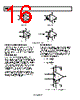
17 / 20 page  AD8236 Rev. 0 | Page 17 of 20 To eliminate high frequency common-mode signals while using smaller source resistors, a low-pass RC network can be placed at the input of the instrumentation amplifier (see Figure 40). The filter limits the input signal bandwidth according to the following relationship: ) 2 ( π 2 1 G C D DIFF C C C R FilterFreq + + = ) ( π 2 1 G C CM C C R FilterFreq + = Mismatched CC capacitors result in mismatched low-pass filters. The imbalance causes the AD8236 to treat what would have been a common-mode signal as a differential signal. To reduce the effect of mismatched external CC capacitors, select a value of CD greater than 10 times CC. This sets the differential filter frequency lower than the common-mode frequency. R R AD8236 +VS –IN +IN 10µF 0.1µF VOUT REF CC CC CD 1nF 1nF 10nF 4.02kΩ 4.02kΩ Figure 40. RFI Suppression COMMON-MODE INPUT VOLTAGE RANGE The common-mode input voltage range is a function of the input voltages, reference voltage, supplies, and the output of Internal Op Amp A. Figure 34 shows the internal nodes of the AD8236. Figure 20 to Figure 23 show the common-mode voltage ranges for typical supply voltages and gains. If the supply voltages and reference voltage is not represented in Figure 20 to Figure 23, the following methodology can be used to calculate the acceptable common-mode voltage range: 1. Adhere to the input, output, and reference voltage ranges shown in Table 2 and Table 3. 2. Calculate the output of the internal op amp, A. The following equation calculates this output: 4 R kΩ 52.5 2 4 5 G REF DIFF DIFF CM V V V V A − − ⎟ ⎠ ⎞ ⎜ ⎝ ⎛ − = where: VDIFF is defined as the difference in input voltages, VDIFF = VINP − VINM. VCM is defined as the common mode voltage, VCM = (VINP + VINM)/2. If no gain setting resistor, RG, is installed, set RG to infinity. 3. Keep A within 10 mV of either supply rail. This is valid over the −40°C to +125°C temperature range. −VS + 10 mV < A < +VS – 10 mV |
|
|
链接网址 |
| ALLDATASHEET是否为您带来帮助? [ DONATE ] |
关于 Alldatasheet | 广告服务 | 联系我们 | 隐私政策 | 数据表链接 | 链接交换 | 制造商名单 All Rights Reserved©Alldatasheet.com |
| Russian : Alldatasheetru.com | Korean : Alldatasheet.co.kr | Spanish : Alldatasheet.es | French : Alldatasheet.fr | Italian : Alldatasheetit.com Portuguese : Alldatasheetpt.com | Polish : Alldatasheet.pl | Vietnamese : Alldatasheet.vn Indian : Alldatasheet.in | Mexican : Alldatasheet.com.mx | British : Alldatasheet.co.uk | New Zealand : Alldatasheet.co.nz |
|
Family Site : ic2ic.com |
icmetro.com |
 Chinese ▼
 English
 Chinese
 German
 Japanese
 Russian
 Korean
 Spanish
 French
 Italian
 Portuguese
 Polish
 Vietnamese
 Indian
 Mexican
 British
 New Zealand