|
数据搜索系统,热门电子元器件搜索 |
|
|
数据搜索系统,热门电子元器件搜索 |
|
AD8014ARTZ-R2 数据表(PDF) 8 Page - Analog Devices |
|
|
|||||||||||||||||||||||||||||
AD8014ARTZ-R2 数据表(HTML) 8 Page - Analog Devices |
|
|
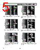
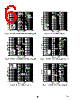
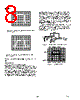
8 / 11 page  AD8014 –8– Note: On Figures 19 and 20 RF = 500 Ω, R S = 50 Ω and C L = 20 pF. APPLICATIONS CD ROM and DVD Photodiode Preamp High speed Multi-X CD ROM and DVD drives require high frequency photodiode preamps for their read channels. To mini- mize the effects of the photodiode capacitance, the low imped- ance of the inverting input of a current feedback amplifier is advantageous. Good group delay characteristics will preserve the pulse response of these pulses. The AD8014, having many ad- vantages, can make an excellent low cost, low noise, low power, and high bandwidth photodiode preamp for these applications. Figure 21 shows the circuit that was used to imitate a photo- diode preamp. A photodiode for this application is basically a high impedance current source that is shunted by a small ca- pacitance. In this case, a high voltage pulse from a Picosecond Pulse Labs Generator that is ac-coupled through a 20 k Ω resis- tor is used to simulate the high impedance current source of a photodiode. This circuit will convert the input voltage pulse into a small charge package that is converted back to a voltage by the AD8014 and the feedback resistor. In this case the feedback resistor chosen was 1.74 k Ω, which is a compromise between maintaining bandwidth and providing sufficient gain in the preamp stage. The circuit preserves the pulse shape very well with very fast rise time and a minimum of overshoot as shown in Figure 22. AD8014 1.74k 20k 49.9 49.9 +5V –5V OUTPUT (10 PROBE) (NO LOAD) 0.1 F INPUT Figure 21. AD8014 as a Photodiode Preamp INPUT DIV 1 2 OUTPUT 500mV/DIV CH1 20.0V CH2 500mV M 25.0ns CH4 380mV TEK RUN: 2.0GS/s ET AVERAGE T[ ] Figure 22. Pulse Response Figure 19. Large Signal Step Response; VS = ±5 V, VO = 4 V Step Figure 20. Large Signal Step Response; VS = +5 V, VO = 2 V Step Rev. C 20V/ |
|
|
链接网址 |
| ALLDATASHEET是否为您带来帮助? [ DONATE ] |
关于 Alldatasheet | 广告服务 | 联系我们 | 隐私政策 | 数据表链接 | 链接交换 | 制造商名单 All Rights Reserved©Alldatasheet.com |
| Russian : Alldatasheetru.com | Korean : Alldatasheet.co.kr | Spanish : Alldatasheet.es | French : Alldatasheet.fr | Italian : Alldatasheetit.com Portuguese : Alldatasheetpt.com | Polish : Alldatasheet.pl | Vietnamese : Alldatasheet.vn Indian : Alldatasheet.in | Mexican : Alldatasheet.com.mx | British : Alldatasheet.co.uk | New Zealand : Alldatasheet.co.nz |
|
Family Site : ic2ic.com |
icmetro.com |
 Chinese ▼
 English
 Chinese
 German
 Japanese
 Russian
 Korean
 Spanish
 French
 Italian
 Portuguese
 Polish
 Vietnamese
 Indian
 Mexican
 British
 New Zealand