|
数据搜索系统,热门电子元器件搜索 |
|
|
数据搜索系统,热门电子元器件搜索 |
|
AD8657ARMZ-R7 数据表(PDF) 21 Page - Analog Devices |
|
|
|||||||||||||||||||||||||||||
AD8657ARMZ-R7 数据表(HTML) 21 Page - Analog Devices |
|
|
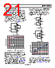
21 / 24 page  Data Sheet AD8657/AD8659 Rev. B | Page 21 of 24 COMPARATOR OPERATION—AD8657 An op amp is designed to operate in a closed-loop configuration with feedback from its output to its inverting input. Figure 72 shows the AD8657 configured as a voltage follower with an input voltage that is always kept at midpoint of the power supplies. The same configuration is applied to the unused channel. A1 and A2 indicate the placement of ammeters to measure supply current. ISY+ refers to the current flowing from the upper supply rail to the op amp, and ISY− refers to the current flowing from the op amp to the lower supply rail. As shown in Figure 73, as expected in normal operating condition, the total current flowing into the op amp is equivalent to the total current flowing out of the op amp, where, ISY+ = ISY− = 36 μA for the dual AD8657 at VSY = 18 V. AD8657 1/2 A1 100kΩ 100kΩ ISY+ +VSY VOUT –VSY ISY– A2 Figure 72. Voltage Follower 0 5 10 15 20 25 30 35 40 0 2 4 6 8 10 12 14 16 18 VSY (V) ISY– ISY+ Figure 73. Supply Current vs. Supply Voltage (Voltage Follower) In contrast to op amps, comparators are designed to work in an open-loop configuration and to drive logic circuits. Although op amps are different from comparators, occasionally an unused section of a dual op amp is used as a comparator to save board space and cost; however, this is not recommended. Figure 74 and Figure 75 show the AD8657 configured as a com- parator, with 100 kΩ resistors in series with the input pins. Any unused channels are configured as buffers with the input voltage kept at the midpoint of the power supplies. The AD8657/AD8659 have input devices that are protected from large differential input voltages by Diode D1 and Diode D2 (refer to Figure 68). These diodes consist of substrate PNP bipolar transistors, and conduct whenever the differential input voltage exceeds approxi- mately 600 mV; however, these diodes also allow a current path from the input to the lower supply rail, thus resulting in an increase in the total supply current of the system. As shown in Figure 76, both configurations yield the same result. At 18 V of power supply, ISY+ remains at 36 μA per dual amplifier, but ISY− increases to 140 μA in magnitude per dual amplifier. AD8657 1/2 A1 100kΩ 100kΩ ISY+ +VSY VOUT –VSY ISY– A2 Figure 74. Comparator A AD8657 1/2 A1 100kΩ 100kΩ ISY+ +VSY VOUT –VSY ISY– A2 Figure 75. Comparator B 0 20 40 60 80 100 120 140 160 0 2 4 6 8 10 12 14 16 18 VSY (V) ISY– ISY+ Figure 76. Supply Current vs. Supply Voltage (AD8657 as a Comparator) Note that 100 kΩ resistors are used in series with the input of the op amp. If smaller resistor values are used, the supply current of the system increases much more. For more details on op amps as comparators, refer to the AN-849 Application Note Using Op Amps as Comparators. |
|
|
链接网址 |
| ALLDATASHEET是否为您带来帮助? [ DONATE ] |
关于 Alldatasheet | 广告服务 | 联系我们 | 隐私政策 | 数据表链接 | 链接交换 | 制造商名单 All Rights Reserved©Alldatasheet.com |
| Russian : Alldatasheetru.com | Korean : Alldatasheet.co.kr | Spanish : Alldatasheet.es | French : Alldatasheet.fr | Italian : Alldatasheetit.com Portuguese : Alldatasheetpt.com | Polish : Alldatasheet.pl | Vietnamese : Alldatasheet.vn Indian : Alldatasheet.in | Mexican : Alldatasheet.com.mx | British : Alldatasheet.co.uk | New Zealand : Alldatasheet.co.nz |
|
Family Site : ic2ic.com |
icmetro.com |
 Chinese ▼
 English
 Chinese
 German
 Japanese
 Russian
 Korean
 Spanish
 French
 Italian
 Portuguese
 Polish
 Vietnamese
 Indian
 Mexican
 British
 New Zealand