|
数据搜索系统,热门电子元器件搜索 |
|
|
数据搜索系统,热门电子元器件搜索 |
|
AD8057ARTZ-R2 数据表(PDF) 14 Page - Analog Devices |
|
|
|||||||||||||||||||||||||||||
AD8057ARTZ-R2 数据表(HTML) 14 Page - Analog Devices |
|
|
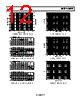
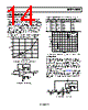
14 / 17 page  Data Sheet AD8057/AD8058 Rev. D | Page 13 of 16 APPLICATIONS INFORMATION DRIVING CAPACITIVE LOADS When driving a capacitive load, most op amps exhibit overshoot in their pulse response. Figure 43 shows the relationship between the capacitive load that results in 30% overshoot and the closed- loop gain of an AD8058. It can be seen that, under the gain = +2 condition, the device is stable with capacitive loads of up to 69 pF. In general, to minimize peaking or to ensure device stability for larger values of capacitive loads, a small series resistor (RS) can be added between the op amp output and the load capacitor (CL) as shown in Figure 44. For the setup shown in Figure 44, the relationship between RS and CL was empirically derived and is shown in Table 4. CLOSED-LOOP GAIN 500 400 0 5 1 2 3 4 300 200 100 RS = 2.4Ω RS = 0Ω Figure 43. Capacitive Load Drive vs. Closed-Loop Gain –2.5V RG RF RS CL VIN = 200mV p-p AD8058 0.1µF 10µF 0.1µF 10µF +2.5V VOUT FET PROBE Figure 44. Capacitive Load Drive Circuit Table 4. Recommended Value for Resistors RS, RF, RG vs. Capacitive Load, CL, Which Results in 30% Overshoot Gain RF RG CL (RS = 0 Ω) CL (RS = 2.4 Ω) 1 100 Ω 11 pF 13 pF 2 100 Ω 100 Ω 51 pF 69 pF 3 100 Ω 50 Ω 104 pF 153 pF 4 100 Ω 33.2 Ω 186 pF 270 pF 5 100 Ω 25 Ω 245 pF 500 pF 10 100 Ω 11 Ω 870 pF 1580 pF 50ns/DIV 100mV –100mV 200mV –200mV +OVERSHOOT 29.0% 100mV/DIV Figure 45. Typical Pulse Response with CL = 65 pF, Gain = +2, and VS = ±2.5 VIDEO FILTER Some composite video signals that are derived from a digital source contain some clock feedthrough that can cause problems with downstream circuitry. This clock feedthrough is usually at 27 MHz, which is a standard clock frequency for both NTSC and PAL video systems. A filter that passes the video band and rejects frequencies at 27 MHz can be used to remove these fre- quencies from the video signal. Figure 46 shows a circuit that uses an AD8057 to create a single 5 V supply, 3-pole Sallen-Key filter. This circuit uses a single RC pole in front of a standard 2-pole active section. To shift the dc operating point to midsupply, ac coupling is provided by R4, R5, and C4. 2 3 0.1µF + 10µF AD8057 7 4 6 +5V +5V R4 10kΩ R5 10kΩ C4 0.1µF R3 49.9Ω R2 499Ω C1 100pF R1 200Ω RF 1kΩ C2 680pF C3 36pF Figure 46. Low-Pass Filter for Video |
|
|
链接网址 |
| ALLDATASHEET是否为您带来帮助? [ DONATE ] |
关于 Alldatasheet | 广告服务 | 联系我们 | 隐私政策 | 数据表链接 | 链接交换 | 制造商名单 All Rights Reserved©Alldatasheet.com |
| Russian : Alldatasheetru.com | Korean : Alldatasheet.co.kr | Spanish : Alldatasheet.es | French : Alldatasheet.fr | Italian : Alldatasheetit.com Portuguese : Alldatasheetpt.com | Polish : Alldatasheet.pl | Vietnamese : Alldatasheet.vn Indian : Alldatasheet.in | Mexican : Alldatasheet.com.mx | British : Alldatasheet.co.uk | New Zealand : Alldatasheet.co.nz |
|
Family Site : ic2ic.com |
icmetro.com |
 Chinese ▼
 English
 Chinese
 German
 Japanese
 Russian
 Korean
 Spanish
 French
 Italian
 Portuguese
 Polish
 Vietnamese
 Indian
 Mexican
 British
 New Zealand