|
数据搜索系统,热门电子元器件搜索 |
|
|
数据搜索系统,热门电子元器件搜索 |
|
AD8601WARTZ-R7 数据表(PDF) 16 Page - Analog Devices |
|
|
|||||||||||||||||||||||||||||
AD8601WARTZ-R7 数据表(HTML) 16 Page - Analog Devices |
|
|
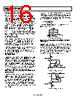
16 / 24 page  AD8601/AD8602/AD8604 Rev. G | Page 16 of 24 INPUT OVERVOLTAGE PROTECTION As with any semiconductor device, if a condition could exist that could cause the input voltage to exceed the power supply, the device’s input overvoltage characteristic must be considered. Excess input voltage energizes the internal PN junctions in the AD860x, allowing current to flow from the input to the supplies. This input current does not damage the amplifier, provided it is limited to 5 mA or less. This can be ensured by placing a resistor in series with the input. For example, if the input voltage could exceed the supply by 5 V, the series resistor should be at least (5 V/5 mA) = 1 kΩ. With the input voltage within the supply rails, a minimal amount of current is drawn into the inputs, which, in turn, causes a negligible voltage drop across the series resistor. Therefore, adding the series resistor does not adversely affect circuit performance. OVERDRIVE RECOVERY Overdrive recovery is defined as the time it takes the output of an amplifier to come off the supply rail when recovering from an overload signal. This is tested by placing the amplifier in a closed-loop gain of 10 with an input square wave of 2 V p-p while the amplifier is powered from either 5 V or 3 V. The AD860x has excellent recovery time from overload conditions. The output recovers from the positive supply rail within 200 ns at all supply voltages. Recovery from the negative rail is within 500 ns at a 5 V supply, decreasing to within 350 ns when the device is powered from 2.7 V. POWER-ON TIME The power-on time is important in portable applications where the supply voltage to the amplifier may be toggled to shut down the device to improve battery life. Fast power-up behavior ensures that the output of the amplifier quickly settles to its final voltage, improving the power-up speed of the entire system. When the supply voltage reaches a minimum of 2.5 V, the AD860x settles to a valid output within 1 μs. This turn-on response time is faster than many other precision amplifiers, which can take tens or hundreds of microseconds for their outputs to settle. USING THE AD8602 IN HIGH SOURCE IMPEDANCE APPLICATIONS The CMOS rail-to-rail input structure of the AD860x allows these amplifiers to have very low input bias currents, typically 0.2 pA. This allows the AD860x to be used in any application that has a high source impedance or must use large value resistances around the amplifier. For example, the photodiode amplifier circuit shown in Figure 56 requires a low input bias current op amp to reduce output voltage error. The AD8601 minimizes offset errors due to its low input bias current and low offset voltage. The current through the photodiode is proportional to the incident light power on its surface. The 4.7 MΩ resistor converts this current into a voltage, with the output of the AD8601 increasing at 4.7 V/μA. The feedback capacitor reduces excess noise at higher frequencies by limiting the bandwidth of the circuit to () F C π BW Ω M 7 . 4 2 1 = (1) Using a 10 pF feedback capacitor limits the bandwidth to approximately 3.3 kHz. AD8601 10pF (OPTIONAL) VOUT 4.7V/µA 4.7M Ω D1 Figure 56. Amplifier Photodiode Circuit HIGH SIDE AND LOW SIDE, PRECISION CURRENT MONITORING Because of its low input bias current and low offset voltage, the AD860x can be used for precision current monitoring. The true rail-to-rail input feature of the AD860x allows the amplifier to monitor current on either the high side or the low side. Using both amplifiers in an AD8602 provides a simple method for monitoring both current supply and return paths for load or fault detection. Figure 57 and Figure 58 demonstrate both circuits. 1/2 AD8602 RETURN TO GROUND RSENSE 0.1 Ω R1 100 Ω R2 249k Ω Q1 2N3904 MONITOR OUTPUT 3V 3V Figure 57. Low-Side Current Monitor 3V IL V+ 3V MONITOR OUTPUT R1 100 Ω R2 2.49k Ω RSENSE 0.1 Ω Q1 2N3905 1/2 AD8602 Figure 58. High-Side Current Monitor |
|
|
链接网址 |
| ALLDATASHEET是否为您带来帮助? [ DONATE ] |
关于 Alldatasheet | 广告服务 | 联系我们 | 隐私政策 | 数据表链接 | 链接交换 | 制造商名单 All Rights Reserved©Alldatasheet.com |
| Russian : Alldatasheetru.com | Korean : Alldatasheet.co.kr | Spanish : Alldatasheet.es | French : Alldatasheet.fr | Italian : Alldatasheetit.com Portuguese : Alldatasheetpt.com | Polish : Alldatasheet.pl | Vietnamese : Alldatasheet.vn Indian : Alldatasheet.in | Mexican : Alldatasheet.com.mx | British : Alldatasheet.co.uk | New Zealand : Alldatasheet.co.nz |
|
Family Site : ic2ic.com |
icmetro.com |
 Chinese ▼
 English
 Chinese
 German
 Japanese
 Russian
 Korean
 Spanish
 French
 Italian
 Portuguese
 Polish
 Vietnamese
 Indian
 Mexican
 British
 New Zealand