|
数据搜索系统,热门电子元器件搜索 |
|
|
数据搜索系统,热门电子元器件搜索 |
|
ADP1660ACBZ-R7 数据表(PDF) 18 Page - Analog Devices |
|
|
|||||||||||||||||||||||||||||
ADP1660ACBZ-R7 数据表(HTML) 18 Page - Analog Devices |
|
|
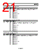
18 / 28 page  ADP1660 Data Sheet Rev. 0 | Page 18 of 28 REGISTER MAP The highest bit number (7) represents the most significant bit; the lowest bit number (0) represents the least significant bit. Table 11. Register Map Address Register Name Bit 7 Bit 6 Bit 5 Bit 4 Bit 3 Bit 2 Bit 1 Bit 0 0x00 Design information DEVICE_ID REV_ID 0x01 Output mode IL_PEAK STR_LV STR_MOD STR_POL LED_MOD 0x02 GPIO and timer LED_SD TEST_SR IO_CFG FL_TIM 0x03 Additional features CL_SOFT DYN_OVP SW_LO FREQ_FB IL_DC IL_DC_EN 0x04 Low battery mode enable Reserved V_BATT_WINDOW V_VB_LO 0x05 Low battery mode current Reserved I_VB_LO 0x06 LED1 flash current Reserved I_FL1 0x07 LED1 TxMASK current Reserved I_TX1 0x08 LED1 torch/assist current Reserved I_TOR1 0x09 LED2 flash current Reserved I_FL2 0x0A LED2 TxMASK current Reserved I_TX2 0x0B LED2 torch/assist current Reserved I_TOR2 0x0C Fault information FL_OVP FL_SC FL_OT FL_TO FL_TX FL_VB_LO FL_IL FL_IDC 0x0D LED1 flash current fault readback Reserved FL_I_FL1 0x0E LED2 flash current fault readback Reserved FL_I_FL2 0x0F LED enable mode Reserved LED2_EN LED1_EN REGISTER DETAILS Table 12. Design Information Register (Register 0x00) Bits Bit Name Access Description [7:3] DEVICE_ID R Device ID for the ADP1660 (00011). [2:0] REV_ID R Revision ID. Table 13. Output Mode Register (Register 0x01) Bits Bit Name Access Description [7:6] IL_PEAK R/W These bits set the inductor peak current limit. 00 = 2.25 A. 01 = 2.75 A. 10 = 3.25 A (default). 11 = 3.5 A. 5 STR_LV R/W This bit sets the sensitivity for the STROBE pin. 0 = edge sensitive. 1 = level sensitive (default). 4 STR_MOD R/W This bit sets the strobe mode. 0 = software strobe mode; software flash occurs when the output is enabled in flash mode. 1 = hardware strobe mode; the STROBE pin must go high for flash (default). 3 STR_POL R/W This bit sets the polarity of the STROBE pin. 0 = active low. 1 = active high (default). [2:0] LED_MOD R/W These bits set the LED output mode. 000 = standby mode (default). 001 = fixed 5 V output mode. 010 = assist light mode. 011 = flash mode. 100 = independent trigger mode with timeout enabled. 101 = independent trigger mode with timeout disabled. 110 = fixed 5 V output mode with torch mode (total output current must be below 500 mA). 111 = reserved. |
|
|
链接网址 |
| ALLDATASHEET是否为您带来帮助? [ DONATE ] |
关于 Alldatasheet | 广告服务 | 联系我们 | 隐私政策 | 数据表链接 | 链接交换 | 制造商名单 All Rights Reserved©Alldatasheet.com |
| Russian : Alldatasheetru.com | Korean : Alldatasheet.co.kr | Spanish : Alldatasheet.es | French : Alldatasheet.fr | Italian : Alldatasheetit.com Portuguese : Alldatasheetpt.com | Polish : Alldatasheet.pl | Vietnamese : Alldatasheet.vn Indian : Alldatasheet.in | Mexican : Alldatasheet.com.mx | British : Alldatasheet.co.uk | New Zealand : Alldatasheet.co.nz |
|
Family Site : ic2ic.com |
icmetro.com |
 Chinese ▼
 English
 Chinese
 German
 Japanese
 Russian
 Korean
 Spanish
 French
 Italian
 Portuguese
 Polish
 Vietnamese
 Indian
 Mexican
 British
 New Zealand