|
数据搜索系统,热门电子元器件搜索 |
|
|
数据搜索系统,热门电子元器件搜索 |
|
LT1370IR 数据表(PDF) 11 Page - Linear Technology |
|
|
|||||||||||||||||||||||||||||
LT1370IR 数据表(HTML) 11 Page - Linear Technology |
|
|
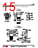
11 / 16 page  11 LT1370 APPLICATIO S I FOR ATIO Layout Considerations For maximum efficiency, LT1370 switch rise and fall times are made as short as possible. To prevent radiation and high frequency resonance problems, proper layout of the components connected to the switch node is essential. B field (magnetic) radiation is minimized by keeping output diode, switch pin and output bypass capacitor leads as short as possible. Figure 3 shows recommended posi- tions for these components. E field radiation is kept low by minimizing the length and area of all traces connected to the switch pin. A ground plane should always be used under the switcher circuitry to prevent interplane coupling. The high speed switching current path is shown schemati- cally in Figure 4. Minimum lead length in this path is essential to ensure clean switching and low EMI. The path including the switch, output diode and output capacitor is the only one containing nanosecond rise and fall times. Keep this path as short as possible. More Help For more detailed information on switching regulator circuits, please see Application Note 19. Linear Technology also offers a computer software program, SwitcherCAD TM, to assist in designing switching convert- ers. In addition, our Applications Department is always ready to lend a helping hand. Figure 4 LOAD VOUT L1 SWITCH NODE LT1370 • F04 VIN HIGH FREQUENCY CIRCULATING PATH VIN NFB GND FB VSW VC S/S C D KEEP PATH FROM VSW, OUTPUT DIODE, OUTPUT CAPACITORS AND GROUND RETURN AS SHORT AS POSSIBLE C LT1370 • F03 Figure 3. Layout Considerations— R Package SwitcherCAD is a trademark of Linear Technology Corporation. |
|
|
链接网址 |
| ALLDATASHEET是否为您带来帮助? [ DONATE ] |
关于 Alldatasheet | 广告服务 | 联系我们 | 隐私政策 | 数据表链接 | 链接交换 | 制造商名单 All Rights Reserved©Alldatasheet.com |
| Russian : Alldatasheetru.com | Korean : Alldatasheet.co.kr | Spanish : Alldatasheet.es | French : Alldatasheet.fr | Italian : Alldatasheetit.com Portuguese : Alldatasheetpt.com | Polish : Alldatasheet.pl | Vietnamese : Alldatasheet.vn Indian : Alldatasheet.in | Mexican : Alldatasheet.com.mx | British : Alldatasheet.co.uk | New Zealand : Alldatasheet.co.nz |
|
Family Site : ic2ic.com |
icmetro.com |
 Chinese ▼
 English
 Chinese
 German
 Japanese
 Russian
 Korean
 Spanish
 French
 Italian
 Portuguese
 Polish
 Vietnamese
 Indian
 Mexican
 British
 New Zealand