|
数据搜索系统,热门电子元器件搜索 |
|
|
数据搜索系统,热门电子元器件搜索 |
|
LT1500CS-5 数据表(PDF) 8 Page - Linear Technology |
|
|
|||||||||||||||||||||||||||||
LT1500CS-5 数据表(HTML) 8 Page - Linear Technology |
|
|
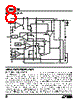
8 / 16 page  8 LT1500/LT1501 BLOCK DIAGRAM – + – + – + BIAS 1.265V REFERENCE + BURST COMPARATOR NEGATIVE ERROR AMP ERROR AMP CURRENT COMPARATOR FIXED HYSTERESIS 100k 150pF VC FB NFB GND 100k S1 I1 I2 VARIABLE HYSTERESIS ISENSE SW PGND R2 Q1 R1 18mV RSENSE 0.28 Ω Rh IN SYNC LBO 1.24V 0.75V SHDN LBI OUTPUT LTC1500/01 • BD APPLICATIONS INFORMATION OPERATION (SEE BLOCK DIAGRAM) The LT1500 uses a current mode architecture without the need for an internal oscillator. Switching frequency is determined by the value of the external inductor used. This technique allows the selection of an operating frequency best suited to each application and considerably simplifies the internal circuitry needed. It also eliminates a subharmonic oscillation problem common to all fixed frequency (clocked) current mode switchers. In addition, it allows for high efficiency micropower operation while maintaining higher operating frequencies. Because the power switch (Q1) is grounded, the basic topology used will normally be a boost converter with output voltage always higher than the input voltage. Special topologies such as the SEPIC, flyback and Cuk converter can also be used when the output voltage may not always be higher than the input or when full shutdown of the output voltage is needed. Operation as a boost converter is as follows. Assume that inductor current is continuous, meaning that it never drops to zero. When the switch is on, inductor current will increase with voltage across the inductor equal to VIN. When the switch is off inductor current will decrease with inductor voltage equal to VOUT – VIN. Switching frequency will be determined by the inductor |
|
|
链接网址 |
| ALLDATASHEET是否为您带来帮助? [ DONATE ] |
关于 Alldatasheet | 广告服务 | 联系我们 | 隐私政策 | 数据表链接 | 链接交换 | 制造商名单 All Rights Reserved©Alldatasheet.com |
| Russian : Alldatasheetru.com | Korean : Alldatasheet.co.kr | Spanish : Alldatasheet.es | French : Alldatasheet.fr | Italian : Alldatasheetit.com Portuguese : Alldatasheetpt.com | Polish : Alldatasheet.pl | Vietnamese : Alldatasheet.vn Indian : Alldatasheet.in | Mexican : Alldatasheet.com.mx | British : Alldatasheet.co.uk | New Zealand : Alldatasheet.co.nz |
|
Family Site : ic2ic.com |
icmetro.com |
 Chinese ▼
 English
 Chinese
 German
 Japanese
 Russian
 Korean
 Spanish
 French
 Italian
 Portuguese
 Polish
 Vietnamese
 Indian
 Mexican
 British
 New Zealand