|
数据搜索系统,热门电子元器件搜索 |
|
|
数据搜索系统,热门电子元器件搜索 |
|
LTC1663C 数据表(PDF) 5 Page - Linear Technology |
|
|
|||||||||||||||||||||||||||||
LTC1663C 数据表(HTML) 5 Page - Linear Technology |
|
|
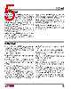
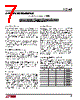
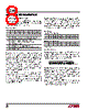
5 / 12 page  5 LTC1663 VCC (Pin 5, Pin 4 on SOT-23): Power Supply. 2.7V ≤ VCC ≤ 5.5V. Also used as the reference voltage input when the part is programmed to use VCC as the reference. AD0 (Pin 6): Slave Address Select Bit 0. Tie this pin to either VCC or GND to modify the corresponding bit of the LTC1663’s slave address. GND (Pin 7, Pin 2 on SOT-23): System Ground. VOUT (Pin 8, Pin 3 on SOT-23): Voltage Output. Buffered rail-to-rail DAC output. PIN FUNCTIONS SDA (Pin 1, Pin 1 on SOT-23): Serial Data Bidirectional Pin. Data is shifted into the SDA pin and acknowledged by the SDA pin. High impedance pin while data is shifted in. Open-drain N-channel output during acknowledgment. Requires a pull-up resistor or current source to VCC. AD1 (Pin 2): Slave Address Select Bit 1. Tie this pin to either VCC or GND to modify the corresponding bit of the LTC1663’s slave address. AD2 (Pin 3): Slave Address Select Bit 2. Tie this pin to either VCC or GND to modify the corresponding bit of the LTC1663’s slave address. SCL (Pin 4, Pin 5 on SOT-23): Serial Clock Input Pin. Data is shifted into the SDA pin at the rising edges of the clock. This high impedance pin requires a pull-up resistor or current source to VCC. DEFINITIONS zero. The INL error at a given input code is calculated as follows: INL = [VOUT – VOS – (VFS – VOS)(code/1023)]/LSB Where VOUT is the output voltage of the DAC measured at the given input code. Least Significant Bit (LSB): The ideal voltage difference between two successive codes. LSB = VREF/1024 Resolution (n): Defines the number of DAC output states (2n) that divide the full-scale range. Resolution does not imply linearity. Voltage Offset Error (VOS): Nominally, the voltage at the output when the DAC is loaded with all zeros. A single supply DAC can have a true negative offset, but the output cannot go below zero (see Applications Information). For this reason, single supply DAC offset is measured at the lowest code that guarantees the output will be greater than zero. Differential Nonlinearity (DNL): The difference between the measured change and the ideal 1LSB change for any two adjacent codes. The DNL error between any two codes is calculated as follows: DNL = ( ∆VOUT – LSB)/LSB Where ∆VOUT is the measured voltage difference between two adjacent codes. Digital Feedthrough: The glitch that appears at the analog output caused by AC coupling from the digital inputs when they change state. The area of the glitch is specified in (nV)(sec). Full-Scale Error (FSE): The deviation of the actual full- scale voltage from ideal. FSE includes the effects of offset and gain errors (see Applications Information). Integral Nonlinearity (INL): The deviation from a straight line passing through the endpoints of the DAC transfer curve (Endpoint INL). Because the output cannot go below zero, the linearity is measured between full scale and the lowest code that guarantees the output will be greater than |
|
|
链接网址 |
| ALLDATASHEET是否为您带来帮助? [ DONATE ] |
关于 Alldatasheet | 广告服务 | 联系我们 | 隐私政策 | 数据表链接 | 链接交换 | 制造商名单 All Rights Reserved©Alldatasheet.com |
| Russian : Alldatasheetru.com | Korean : Alldatasheet.co.kr | Spanish : Alldatasheet.es | French : Alldatasheet.fr | Italian : Alldatasheetit.com Portuguese : Alldatasheetpt.com | Polish : Alldatasheet.pl | Vietnamese : Alldatasheet.vn Indian : Alldatasheet.in | Mexican : Alldatasheet.com.mx | British : Alldatasheet.co.uk | New Zealand : Alldatasheet.co.nz |
|
Family Site : ic2ic.com |
icmetro.com |
 Chinese ▼
 English
 Chinese
 German
 Japanese
 Russian
 Korean
 Spanish
 French
 Italian
 Portuguese
 Polish
 Vietnamese
 Indian
 Mexican
 British
 New Zealand