|
数据搜索系统,热门电子元器件搜索 |
|
|
数据搜索系统,热门电子元器件搜索 |
|
MC34018G-R28-R 数据表(PDF) 3 Page - Unisonic Technologies |
|
|
|||||||||||||||||||||||||||||
MC34018G-R28-R 数据表(HTML) 3 Page - Unisonic Technologies |
|
|
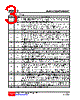
3 / 8 page  MC34018 LINEAR INTEGRATED CIRCUIT UNISONICTECHNOLOGIESCO.,LTD 3 of 8 www.unisonic.com.tw QW-R108-006.E PIN DESCRIPTION PIN NO. PIN NAME DESCRIPTION 1 RR A resistor to ground provides a reference current for the transmit and receive attenuators 2 RTX A resistor to ground determines the nominal gain of the transmit attenuator, the transmit channel gain is inversely proportional to RTX resistance. 3 TXI Transmit Attenuator Input, Input resistance is nominally 5.0kΩ. 4 TXO Transmit Attenuator Output, The TXO output signal drivers the input of transmit level detcetor, as well as the external circuit which drivers the telephone line. 5 TLI Transmit Level detector Input. An external resistor ac coupled to The TLI pin sets the detection level. Decreasing this resistor increases the sensitivity to transmit channel signals. 6 TLO Transmit Level detector Output. The external resistor and capacitor set the time the comparator will hold the system in the transmit mode after speech ceases. 7 RLI Receive Level detector Input. An external resistor ac coupled to The RLI pin sets the detection level. Decreasing this resistor increases the sensitivity to receive channel signals. 8 RLO Receive Level detector Output. The external resistor and capacitor set the time the comparator will hold the system in the receive mode after speech ceases. 9 MCI Microphone amplifier input. Input impedance is nominally 10kΩ and the dc bias voltage is approximately equal to VB 10 MCO Microphone amplifier output. The MIC amp gain is internally set at 34dB (50V/V). 11 CP1 A parallel resistor and capacitor connected between this pin and VCC holds a voltage corresponding to the background noise level. The transmit detector compares the CP1 voltage with the speech signal from CP2. 12 CP2 A capacitor at this pin peak detects the speech signals for comparison with the background noise level held at CP1. 13 XDI Input to the transmit detector system. The microphone amplifier output is ac coupled to the XDI pin through an external resistor. 14 SKG High current ground pin for the speaker amplifier output stage. The SKG voltage should be within 10mV of the ground voltage at pin 22. 15 SKO Speaker amplifier output. The SKO pin will source and sink up to 100mA when ac coupled to the speaker. The speaker amplifier gain is internally set at 34dB (50V/V). 16 V+ Input DC supply voltage. V+ can be powered from Tip and Ring if an ac decoupling inductor is used to prevent loading ac line signals. The required V+ voltage is 6.0V to 11V (7.5V nominal) at 7.0mA. 17 AGC A capacitor from this pin to VB stabilizes the speaker amplifier gain control loop, and additionally controls the attack and decay time of this circuit. The gain control loop limits the speaker amplifier input to prevent clipping at SKO. The internal resistance at AGC pin is nominally 110kΩ. 18 CS Digital chip select input. When at a logic "0" (<0.7V) the VCC regulator is enabled. When at a logic "1" (>1.6V),the chip is in the standby mode drawing 0.5mA.An open CS pin is a logic "0".Input impedance is nominally 140k ohms. The input voltage should not exceed 11V. 19 SKI Input to the speaker amplifier. Input impedance is nominally 20kΩ. 20 VCC A 5.4V regulated output which powers all circuits except the speaker amplifier output stage. VCC can be used to power external circuitry such as a microprocessor(3.0mA max.) A filter capacitor is required. The UTC MC34018 can be powered by a separate regulated supply by connecting V+ and VCC to a voltage between 4.5V and 6.5V while maintaining CS at a logic "1". 21 VB An output voltage equal to approximately VCC/2 which series as an analog ground for the speakerphone system. Up to 1.5mA of external load current may be sourced from VB. Output impedance is 250 ohms. A filter capacitor is required. 22 GND Ground pin for the IC(except the speaker amplifier) |
|
|
链接网址 |
| ALLDATASHEET是否为您带来帮助? [ DONATE ] |
关于 Alldatasheet | 广告服务 | 联系我们 | 隐私政策 | 数据表链接 | 链接交换 | 制造商名单 All Rights Reserved©Alldatasheet.com |
| Russian : Alldatasheetru.com | Korean : Alldatasheet.co.kr | Spanish : Alldatasheet.es | French : Alldatasheet.fr | Italian : Alldatasheetit.com Portuguese : Alldatasheetpt.com | Polish : Alldatasheet.pl | Vietnamese : Alldatasheet.vn Indian : Alldatasheet.in | Mexican : Alldatasheet.com.mx | British : Alldatasheet.co.uk | New Zealand : Alldatasheet.co.nz |
|
Family Site : ic2ic.com |
icmetro.com |
 Chinese ▼
 English
 Chinese
 German
 Japanese
 Russian
 Korean
 Spanish
 French
 Italian
 Portuguese
 Polish
 Vietnamese
 Indian
 Mexican
 British
 New Zealand