|
数据搜索系统,热门电子元器件搜索 |
|
|
数据搜索系统,热门电子元器件搜索 |
|
LM2941CSX/NOPB 数据表(PDF) 13 Page - Texas Instruments |
|
|
|
|||||||||||||||||||||||||||||
LM2941CSX/NOPB 数据表(HTML) 13 Page - Texas Instruments |
|
|
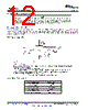
13 / 30 page  LM2941, LM2941C www.ti.com SNVS770I – JUNE 1999 – REVISED JANUARY 2015 8.2.2 Detailed Design Procedure 8.2.2.1 Output Capacitor A tantalum capacitor with a minimum capacitance value of 22 μF, and ESR in the range of 0.01 Ω to 5 Ω, is required at the output pin for loop stability. It must be located less than 1 cm from the device. There is no limitation on any additional capacitance. Alternately, a high quality X5R/X7R 22 μF ceramic capacitor may be used for the output capacitor only if an appropriate value of series resistance is added to simulate the ESR requirement. The ceramic capacitor selection must include an appropriate voltage de-rating of the capacitance value due to the applied output voltage. The series resistor (for ESR simulation) should be in the range of 0.1 Ω to 1 Ω. 8.2.2.2 Setting the Output Voltage The output voltage range is 5 V to 20 V and is set by the two external resistors, R1 and R2. See the Figure 18. The output voltage is given by the formula: VOUT = VREF × ((R1 + R2) / R1) where • VREF is typically 1.275 V (1) Using 1 k Ω for R1 will ensure that the bias current error of the adjust pin will be negligible. Using a R1 value higher than 10 k Ω may cause the output voltage to shift across temperature due to variations in the adjust pin bias current. Calculating the upper resistor (R2) value of the pair when the lower resistor (R1) value is known is accomplished with the following formula: R2 = R1 × ((VOUT / VREF) – 1) (2) The resistors used for R1 and R2 should be high quality, tight tolerance, and with matching temperature coefficients. It is important to remember that, although the value of VREF is ensured, the final value of VOUT is not. The use of low quality resistors for R1 and R2 can easily produce a VOUT value that is unacceptable. 8.2.3 Application Curves Figure 19. Low Voltage Behavior Figure 20. Output at Voltage Extremes Copyright © 1999–2015, Texas Instruments Incorporated Submit Documentation Feedback 13 Product Folder Links: LM2941 LM2941C |
|
|
链接网址 |
| ALLDATASHEET是否为您带来帮助? [ DONATE ] |
关于 Alldatasheet | 广告服务 | 联系我们 | 隐私政策 | 数据表链接 | 链接交换 | 制造商名单 All Rights Reserved©Alldatasheet.com |
| Russian : Alldatasheetru.com | Korean : Alldatasheet.co.kr | Spanish : Alldatasheet.es | French : Alldatasheet.fr | Italian : Alldatasheetit.com Portuguese : Alldatasheetpt.com | Polish : Alldatasheet.pl | Vietnamese : Alldatasheet.vn Indian : Alldatasheet.in | Mexican : Alldatasheet.com.mx | British : Alldatasheet.co.uk | New Zealand : Alldatasheet.co.nz |
|
Family Site : ic2ic.com |
icmetro.com |
 Chinese ▼
 English
 Chinese
 German
 Japanese
 Russian
 Korean
 Spanish
 French
 Italian
 Portuguese
 Polish
 Vietnamese
 Indian
 Mexican
 British
 New Zealand